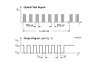
I need to design demodulation circuit for the given digtal waveforms in the attached figure. The digital signals (PWM) will be in the frequency range of 5khz 500khz. The signal will be received using a photodetector. I would like to be able to scan select frequencies and detect a modulated signal at the reference frequency. I have some questions regarding the best method of doing this.
1. What are the most common and reliable demoduation techniques for an application such as this? Bandpass filters, PLL's?
2. What are the pros and cons to using a simple discrete bandpass filter to determine whether there is energy whithin the predefined band and having it fed to a comparator to feed a high - lo output when threshold level of input is met? I realize that this may be unfeasable as I would have many components for if I were to be checking many frequencies.
3. It looks like an IC like the LM567(https://www.electro-tech-online.com/custompdfs/2009/07/LM567.pdf) would be a good option for this. But only detects at 1 frequency based upon the input capacitor - resistors. But, what i would like to do beyond what the LM567 can do is to vary the reference signal of detection so that i can accomplish a scan of frequencies.
4. It seems reasonble that I could send a PWM signal as the reference from a uC to a PLL and be given feedback (VCO error voltage) as to whether or not there is a signal at the reference frequency. Could someone recommend a PLL that would work in such a configuration?
Thanks