Continue to Site

Welcome to our site!

Electro Tech is an online community (with over 170,000 members) who enjoy talking about and building electronic circuits, projects and gadgets. To participate you need to register. Registration is free. Click here to register now.

  • Welcome to our site! Electro Tech is an online community (with over 170,000 members) who enjoy talking about and building electronic circuits, projects and gadgets. To participate you need to register. Registration is free. Click here to register now.

Digital guitar amp mod

Status
Not open for further replies.

jjam47

New Member
Hello,
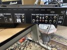
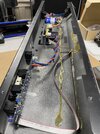
I am new to this forum. I recently acquired a behringer V tone GMX212 guitar amp that has had the preamp section removed I’m assuming because it wasn’t working but the power amp and the speakers work fine. The master volume knob was removed along with the front panel so if I plug a pedal or some other type of preamp into the slave ins on the back panel I get full volume from the power section. I would like to convert this amp into sort of an frfr style cabinet but I would have to add a master volume somehow. Does anyone know if that is doable and how ? Thanks
 
You may only need a 10K or 100K potentiometer.

Connect the external signal to the clockwise end, signal ground & input ground to the anticlockwise end, amp input to the pot wiper.

If you can find R25 & R41 (centre top, page 3), that are in line with the external inputs from the slave in sockets, you could remove those and add the pots in those circuits, plus using the grounds from either the sockets or X17 pins.


Photos of the amp internals could be useful?

That amp is supposed to have a digital effects module - it could be that missing & the rest still intact, but no connections from inputs to outputs??
 
Thanks for the reply,
All the rear panel ins/outs are intact but the front panel circuit board with all the pots is missing. I would just like to utilize the power section and speakers anyway in a custom cabinet. It is a dual 60 watt amp so I would like to have the option to hook in a stereo or mono source. Is there anyway you can draw up a crude schematic or modify the existing schematic for me to follow ? Thanks for your help. I am working out of town but can supply photos asap.
 
Thanks for your help. I am working out of town but can supply photos asap.
OK, as soon as you post photos so we can see how the sockets are connected, it will be possible to come up with a practical solution.

I'd rather avoid a method that means hacking in to the PCB tracks, if connections are available.
 
I’m not an electronics expert but I have lots of experience tinkering with the stuff that I do understand so a simplified drawing of any circuit modifications would keep me from screwing it up. I will get some detailed photos asap. Would this pot be suitable ? (Link to pic)
Dual Audio Potentiometer 1K Ohm https://a.co/d/4ns3K8P...thanks for your patience and knowledge.
 
1663105611041.png


I think those carbon audo taper pots will do from any headphone jack or amplified guitar signal box to your power amp 1k input impedance.or more. I believe it is 2k.

Choose any style of connectors you wish. Gold plated or nickel plated.

1/4" jack or 3.5mm or DIN or whatever.

Info on Pots < Log is better than Audio taper but harder to find.

With a certain ratio of Pot R / fixedR , you can make a log or audio like taper with a linear pot

By choosing a 10K linear POTs (instead of 1k) with 2k power Amp load, you have a taper of 10/2=5

with 1k pot and 2k fixed, you have a taper of 0.5 between 0 linear and 1.

1663106835352.png
 
Last edited:
Tony - the OP starts out by saying he's using the "Slave in" which to me means this section, 33K input load. I'm not sure where you get 2K from?

This part also has some convenient connections between the jacks and PA inputs, IF they are something that can be intercepted, which is why I was hoping for photos.


Behringer_amp_mod.jpg
 
Then it would be 22K 33k input impedance so he could use a 100k Linear dual pot. if that is true.

I was thinking the preamp was missing.
1663156516844.png
 
Last edited:
Sorry bout the holdup...attached are some pics of what is left in the chassis...I would like to eliminate anything there that I don’t need and just keep...power switch/inputs/master volume/power amp/speakers...if possible...there is a large heat sink on the bottom of the chassis which I will use also...
 

Attachments

  • 27789458-5FC6-493E-8DAA-8278368390CD.jpeg
    27789458-5FC6-493E-8DAA-8278368390CD.jpeg
    3.1 MB · Views: 221
  • E4BC9762-C799-4164-A27C-385552E0C215.jpeg
    E4BC9762-C799-4164-A27C-385552E0C215.jpeg
    3.9 MB · Views: 187
  • C9060F55-63D0-487D-8F66-8DEFA1FC78D0.jpeg
    C9060F55-63D0-487D-8F66-8DEFA1FC78D0.jpeg
    3.6 MB · Views: 195
  • 72BC56C2-76B2-464B-BBCC-ECE2D365028C.jpeg
    72BC56C2-76B2-464B-BBCC-ECE2D365028C.jpeg
    5 MB · Views: 200
  • 7A5591C0-EBA6-4F4E-8C1E-CA0D553F571B.jpeg
    7A5591C0-EBA6-4F4E-8C1E-CA0D553F571B.jpeg
    2.3 MB · Views: 194
OK, I see what you mean!
The disconnection from whatever else was in the chassis is at "X22", a ribbon cable connector just below the remaining ribbon link to the power amp.

If you look as page 3 of the schematic, it still has the aux / tape input circuit, but that only goes to pins 7 & 9 on X22, then the next vertical column of four opamp stages is missing, and the next existing connections are at X22 10 & 11 for the power amp in via the Slave in sockets. The headphone amp / tape out is still there!


You could connect 10K volume pots just to the X22 pins.

Clockwise ends 7 & 9, wipers to 10 & 11, anticlockwise ends to 3 & 4 (which are at the bottom right corner of page 1).
That should get the aux / tape inputs working with volume control.

You can adjust the max gain of those using the presets in the aux in circuit (VR1A & VR1B), to match it to whatever is feeding it.
 
Thanks for your help,
There is an aux volume control knob on the back panel that controls the input of whatever is plugged into it...I believe that is what you are referring to at the end of your message...can I ask a couple of rookie questions ?
Why wouldn’t the existing volume pot on the back panel for the aux in serve the same purpose as the volume pots that would be installed between the x22 pins ?
Also why can the volume pots not be installed between x17 and x1 pins at the slave ins and forget about the aux/tape ins ?
Can you verify that this crude schematic is correct ? Thanks very much for your time.
23E0D7F9-E218-4178-B1C3-971D94C7B4EB.jpeg

I just noticed on the schematic that the 7/9 pins are actually 7/8 unless I’m seeing something wrong.
 
why can the volume pots not be installed between x17 and x1 pins at the slave ins and forget about the aux/tape ins ?

I was trying to avoid causing more damage; cutting in to the existing ribbon is a bit tricky, I'd rather avoid that. Also the other inputs give a bit of optional gain, if of use.

You diagram looks fine, allowing for it being 7 & 8 as you say.. I did not zoom in far enough on the diagram and misread it as 7 & 9, sorry.
 
Thanks...yes it is so small that I didn’t see it either until I printed those schematics larger. One more dumb question...could the existing volume pot at the aux input on back panel take the place of the missing master volumes ? And then just run jumpers across x22 pins ? Or is that circuit not suitable to control the power amp ? Sorry I wish I was more knowledgeable about the application of the schematics. I’m gonna try your advice and see what we come up with...I’ll keep you posted... thanks a lot for the help.
 
could the existing volume pot at the aux input on back panel take the place of the missing master volumes ? And then just run jumpers across x22 pins ?

Another thing I missed from not zooming in enough! I thought they were onboard presets, rather than an external control...

Yes, it can - just jumper 7 to 10 and 8 to 11.
 
Is there a common way of identifying which pin is which on those moduler ribbon connectors ? I’m having trouble with that. The ribbon cable has a red line on one of the wires...what does that tell me ? Thanks for all the help.
 
Status
Not open for further replies.

Latest threads

New Articles From Microcontroller Tips

Back
Top