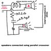
To explain the speaker 'thing' a little more - a speakers impedance is just a nominal value, and it's actual impedance will vary greatly, based mainly on it's inductance. The 8 ohm figure is usually an approximation of the value at 1kHz.
The crossover posted is actually a fairly complex one - the crudest is simply a capacitor feeding the tweeter. While the crossover does effectively put the two in parallel, it's not until a higher frequency, where the drivers impedances (and certainly the bass unit) will be much higher than 8 ohms, and the resultant paralleled impedance will still be higher than 8 ohms.
It's also fairly common for speakers to have low 'dips' in impedance, and some speakers (usually fairly top end ones) may have a reputation for been 'difficult to drive' because of it - but you're likely to be using a top end amplifier anyway, which would usually be able to cope.
So don't over think speaker impedances, it's mainly a 'wild' guess in the first place.
Have a read here:
Impedance, it’s a fairly straight forward concept, all electrical circuits and components resist the flow of electricity (or current) to some degree and the way we measure that resistance is impedance. The unit of measurement of impedance is ohms, often symbolized by the Greek letter omega: Ω...

www.aperionaudio.com
And in particular have a look at the graph of speaker impedance against frequency.