Continue to Site

Welcome to our site!

Electro Tech is an online community (with over 170,000 members) who enjoy talking about and building electronic circuits, projects and gadgets. To participate you need to register. Registration is free. Click here to register now.

  • Welcome to our site! Electro Tech is an online community (with over 170,000 members) who enjoy talking about and building electronic circuits, projects and gadgets. To participate you need to register. Registration is free. Click here to register now.

difference between the circuit

Status
Not open for further replies.

wyl86

New Member
i'm doing a PWM motor control circuit..

i have a problem with the PWM ADJ part.. i would like to know the difference between the circuit with and without diode? and y does the circuit diode works better?

diagrams shown in e attach doc.

thanks
 

Attachments

  • Circuits.doc
    44.5 KB · Views: 339
You did not attach the entire oscillator circuit so your pot with diodes are almost meaningless.

If the oscillator is a 555 IC then the diodes allow separate charge and discharge times for the timing capacitor.

A word Document is for words, not schematics. Please post schematics as a PNG file type.
 
i attach e circuits here

thanks
 

Attachments

  • circuit with diode.jpg
    circuit with diode.jpg
    977.7 KB · Views: 359
  • circuit without diode.jpg
    circuit without diode.jpg
    897.7 KB · Views: 352
Your schematics do not have a part number for the IC but it looks like an NE555 circuit.

The first one changes the duty-cycle of the rectangular-wave output so it produces PWM. Its frequency changes a small amount.
The second one does not change the duty-cycle of its rectangular-wave output so it does not produce PWM. Instead it changes the frequency. Some DC motors change their speed a little when the frequency is changed a lot due to their inductance.
 
Your power supply symbol looks like ground.
Are you using an AC power supply?
 
A battery does not have a fluctuation of 13.4V pk-pk.


He's using the same symbol at his transistor, which seems to imply a DC supply. Confusing.

Where is he indicating this symbol represents a 13.4 V pk-pk voltage? I only see waveforms indicated at the outputs of the 555, not the supply voltages to the IC or transistor. Am I missing something?

I'm still guessing th double lines (one short, one long) represent a single cell battery, like they are supposed to in a proper schemy....which would be just another way of indicating a DC supply of some indeterminate value.

....But I will admit I see pins 4,8 have a waveform drawn and he pk-pk value. If he means for an alternating pulse to be applied here, he shouldn't confuse his drawings with DC symbols. Bad practice.
 
Last edited:
Hi,
I am a newbie ..i am interfacing MCU atmega8l to PC through RS232 ,here i did the loop back test via hyperterminal i didn't get the response from the MCU.
And before communicating to mcu i did the loop back test to the following for these i got the response

Start from the cable and work you way over to the PIC. Use hypertem to do a loopback in each of the following steps. I understand that step 1 will pass and step 4 will fail in your case.

1. Remove the RS232 cable from the Inchworm and short pins 2 and 3 on the cable.

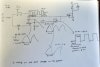
2. If step 1 passed: Remove the MAX232. Look at the schematic and determine which pins on the MAX232 socket connect to 2 and 3 on the DB9. Short these pins at the MAX232 socket. If this works you know the RS232 signal is getting to the MAX232. If not you have bad solder joints between the DB9 and the MAX232 socket.

3. If step 2 passed: Replace the MAX232 and remove the PIC. Short the MAX232 pins that go to TX and RX on the PIC at the MAX232 chip. If this works your MAX232 is working.

and here the 4 th step i tried but i am not able to identify where my communication pbm is?So i need some assitance

4. If step 3 passed: Short the TX and RX pins on the PIC. If this fails you have bad solder joints between the MAX232 and the PIC.

Please would anybody try to help out..
 
twinklu7 If you have a question of your own, please start your own thread.

And wyl86, your symbols for ground and positive supply are backwards.

Try to use these symbols...
**broken link removed**
 
Status
Not open for further replies.

Latest threads

New Articles From Microcontroller Tips

Back
Top