Continue to Site

Welcome to our site!

Electro Tech is an online community (with over 170,000 members) who enjoy talking about and building electronic circuits, projects and gadgets. To participate you need to register. Registration is free. Click here to register now.

  • Welcome to our site! Electro Tech is an online community (with over 170,000 members) who enjoy talking about and building electronic circuits, projects and gadgets. To participate you need to register. Registration is free. Click here to register now.

Difference between Half and Full bridge-Plasma speaker

Status
Not open for further replies.

spitso

Member
To start of what is the difference between half bridge and full bridge in concerns of MOSFET drivers go.

Hi there i have made this following circuit (Plasma Speaker)
**broken link removed**
shortened version of
https://scopeboy.com/tesla/tl494-fullbridge.gif

problem is my MOSFET gets realy hot.....due to the circuit is using half bridge and no mosfet driver. I cannot get the tc4429 ic where i live...any other ideas how i can stop my MOSFET over heating, or maybe how to conect another mosfet driver.

Heres another schematic ive found which someone has added saying it will stop MOSFET overheating/blowing
https://www.instructables.com/files/orig/FVE/I3SC/FR123O01/FVEI3SCFR123O01.png
 
omitting the gate resistor on the FET may help power dissipation slightly, it'll switch faster.
 
i just had a though (maybe a stupid one).

If i attached an amplifer at the end of the circuit to run the MOSFET, would this in anyway help heating or loudness of music????

What would be best conection method

here is simple lm386 amp im planing too use **broken link removed**
 
Probably wouldn't help spitso, also you say it gets very hot but most people don't realize that power electronics are okay to get hot. The max operating temperature of your typical power FET is hotter than a human being can safely touch.
 
I have personally played with that driver and i have found it to waste alot of power and mosfets. I would recommend building this instead **broken link removed** with the half bridge output. The sound quality is excellent and with a god flyback you can run it for 30 min before you have to turn it off.
 
but the MOSFET breaks down and it is a fairly expenisve component to replace (It is on a big heatsink).

Would the amplifier help at all with the MOSFET problem or would it even do anything at all?
 
I wouldn't use an amplifier, I'd use a purpose built Mosfet driver. With the load you're driving though you may just need to buy a bigger fet, it's really hard to tell without scope shots of the gate/drain/source voltages and current through the FET. You're either running the FET too long in it's linear region, or you're pushing too much current through it.
 
i unfortuneately dont have a ocilioscope. But current isnt a problem because i used a bench top powersupply and limited current at 3 amps, irf540 which im using can handle 33amps. So currents not the problem, must be MOSFET getting wrongly switched.

I live in australia and cant get a tc4429 for this schematic(https://scopeboy.com/tesla/tl494-fullbridge.gif).

What other cheap mosfet driver can i use and if possible can you provide me with conecting it, continuing on from this circuit **broken link removed**
as i am not fimilar with using MOSFET drivers.
 
It's current limited? Have you checked to make sure you're not drawing too much current then? If you draw too much current from the supply the voltage is going to drop and that's going to do all sorts of nasty things to the voltages on your circuit, if your voltage drops too much that mosfet will be in it's linear region regardless of how you drive it. What's the DC resistance of the flyback coil primary?
 
Last edited:
i wound my own coil around the ferrite core using thick wire, 5 turns. I believe my multimeter is broken so cant give you accurate reading. Ive also tried a laptop battery which is 12v at around 10 amps. But the bench top power supply is both current and voltage regulated.
 
5 turns?! No wonder the mosfet is heating up! The DC resistance of the mosfet while on (regardless of what's driving it) is going to be huge compared to the load, so the bulk heating is going to be in the fet. The only way to change that is to alter your primary coil in some way.

Before I can suggest anything what's the turns ratio between primary and secondary what gauge wire are you using and what form are you using for the transformer itself?
 
Last edited:
Its 5 turns of awg 16 copper wire. The transformer is a flyback transformer with internal primary and secondary, but i made my own primary coil on outside of transformer, wrapped around ferrite core. The secondary is unknown windings sorry.

So id have to make the majority of the dc resistance on the load of MOSFET, so im guessing ethier more coils or a small resister.???

attacched is picture of my flyback, coils , MOSFET and heatsink
 

Attachments

  • P05-05-09_17.24.JPG
    P05-05-09_17.24.JPG
    1.1 MB · Views: 2,234
Ok, i have a couple of suggestions. What frequency are you running it at? I would recommend you run it at minimum 100khz and you at least 10 primary turns. As for the driver, it's quite easy to modify into something that may be slightly less confusing. Take the outputs of pins 9/10 and feed them into a ucc37322 (non inverting) and ucc37321 (inverting) mosfet driver pair. Those are very common drivers and should be available all over ebay. Use them in a inverting/non inverting configration to drive a gate drive transformer. Tere is also alot of unnecessary parts added to the bridge so to make it more clear, i have attached a schematic of a standard full bridge layout. Be sure to clamp each gate with 2 back to back 18v zener diodes and add a 5.1Ω in series with each gate. Also, Q2 and Q3 need to have their signal inverted and that's quite easy, you just take it from the opposite side of the gdt. It's standard on all full bridge schematics but hopefully that should give you a good start and should be alot more efficient and reliable.
 

Attachments

  • Full-bridge.png
    Full-bridge.png
    908 bytes · Views: 6,517
What Mosfet are you using as well? You need one with the absolute lowest on resistance you can possibly find.
 
I'm using irf540 as MOSFET. I did a quick google/ebay search for ucc37322 and nothing came up, i live in Victoria, Australia.

The site states that it runs from 5KHz to 45KHz (Variable resistor ,22k ohm ,on pin 6) as it gets tuned past 20KHz the frequency is above af and only leaves the music in af. But you have to play around witht he flyback to find its resonating frequency (which i found is close to the end of af). If you go too high then the spark becomes very weak.
so i doubt 100KHz would work.
 
The IRF540 is like 44mΩ
You should be able to find mosfets that are 2mΩ or so.
 
Last edited:
Hy all

this is my first post on this forum, and i registraded just to explain to you folks how this work's

I was thinking about this problems, and i would like to share with all of you what i have realized.

So, Firstly, i guess manny of you watch the datasheets closly...
As for the mosfet's you need to realize tat thay are a litle diferent constructed then a normal npn transistor.... on the gate yo ucan see the diference... in fact the gate-sourse is charged like a capacitor. in the moment the voltage get's on it it has no resistence and huge current flows (if there is so much current) it behaves like shorted, but, that lasts for a split of a second, and after 5 tau the cup is charged fully, and the gate behaves the same like a cup. so after the gate is charged it draws no current and that's the advantage to the npn's . much less power is needed for driving a mosfet. So you need a driver for a mosfet, you just NEED IT!
And in this schematic: **broken link removed** the mosfet is driven ineficient. that's why the mosfet blows off, after some time... the fact is , the output of a tl494 in that schematic is connected like a pull up driver, and that relly bad.
if you see the funcion block diagram of tl494 you'll see that the gate of the mosfet is connected on the emiter at the pin 9 (and 10) so, it isn't close to be driven correctly . in the fact, the gate charges while the tl494 open's but, after it closes it stay's open, maybe the gate voltage fals a fiew volt's 1 or 2, maybe even 3V, and then the tl494 opens again. and so on... The thing is, the mosfet is opened, while the tl494 is on, it's ok., but it dosen't close just falls a litle bit, ... and while the off time it's floating, and that's why the mosfet blows up and dies! By that said, you realize you should use a driver, and you can use any driver.

The posebilities for driving a mosfet, are a fiew... and thay are all good, some better , some cost more, depending on how much money are you willing to spend...
People mentioned the ucc's and they are great. but, some people can't buy them becose in their countrie, ther isn't a shop, which would have them... but, there are a fiew other good ideas....

you could put the gate of the mosfet on the colector of the tl494 output (puns 8 and 11) and use them like pull down, and that would give the supply current to the gate while charging and the C-E current of the tl494 200mA per chanel, but, i haven't tested this , and there is a big posibility that the discarge current will destroy the tl494, so, that need's to be tested.:D

i tried to make a driver and it works nice. The mosfet isn't ofcors cold. but, it work's and dosen't blows out... it just works. **broken link removed** but, you can use any simular pnp and npn transistors. just you need to concidure the charge and discharge current, ofcors the base current.... You need just to put some heatsinks on them... with a 10 ohm resistor the discharge pnp heet's a bit, but it's ok. that means it work's fine and discarges the mosfet fine.

Some other chips are there to buy like the ucc's but thay are the same, but a litle weeker.


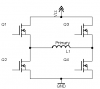
And for the half-bridge, and the h-bridge....
they work the same, the only diference is the half-bridge , work's with half of the supply voltage, and that would mean that half of the supply voltage you will bring to the primary. As for the h-bridge, there you bring the full voltage to the primary......
This circuit, : https://www.instructables.com/files/orig/FVE/I3SC/FR123O01/FVEI3SCFR123O01.png works the sam e like the h-bridge, but without a GDT. or some drivers...and the schematic is verry nice. but you would need to add a gate driver per gate... from the pins 9 and 10


As for the GDT, you need a strong driver for ti, the same like you would drive a singele mosfet,

If you whan't to know something, or you mean i'm saying something wrong, then please Say so,....
 
Status
Not open for further replies.

Latest threads

New Articles From Microcontroller Tips

Back
Top