chrischris
Member
Hi,
I am trying to detect any appliance being turned off or on. I am using SCT013-30 (30A/1V) sensor with 62 ohm burden resistor built in. If I measure the AC voltage with just the sensor (not connected to my circuit, I get 30mV for off and 340mV for on.
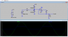
As soon as I connect the circuit to PIC or even connect it to a resistor divider as shown here , the voltage goes to some random value, even up to 16V AC. and -30mV DC. I think it's the noise from the my 12V power adaptor that's effecting it, is there any way I can actually measure that chnage from 30mV AC to 340mV AC and feed it to a PIC ADC ?
I have even tried using LM324 and BC546 to amplify but as soon as I connect CT sensor output to my circuit, it goes all funny!!
p.s. I can't use a battery to drive my circuit I have to use a 12V power adaptor so no way around to the electrical noise. Also the CT sensor has to be non invasive type(or any other sensor for that matter that can serve the purpose).
Thanks,
Chris
I am trying to detect any appliance being turned off or on. I am using SCT013-30 (30A/1V) sensor with 62 ohm burden resistor built in. If I measure the AC voltage with just the sensor (not connected to my circuit, I get 30mV for off and 340mV for on.
As soon as I connect the circuit to PIC or even connect it to a resistor divider as shown here , the voltage goes to some random value, even up to 16V AC. and -30mV DC. I think it's the noise from the my 12V power adaptor that's effecting it, is there any way I can actually measure that chnage from 30mV AC to 340mV AC and feed it to a PIC ADC ?
I have even tried using LM324 and BC546 to amplify but as soon as I connect CT sensor output to my circuit, it goes all funny!!
p.s. I can't use a battery to drive my circuit I have to use a 12V power adaptor so no way around to the electrical noise. Also the CT sensor has to be non invasive type(or any other sensor for that matter that can serve the purpose).
Thanks,
Chris
 I must be interpreting the CT spec differently from you. I read "30A/1V" as meaning "30A will give a 1V output across the burden resistor".