I am using a White & Rodgers 1311 zone valve for a snowmelt system (spec here):
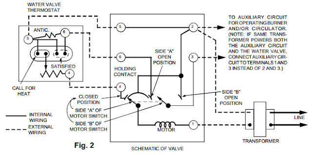
This device is typically controlled by a SPDT relay that connects input pins 4 & 5 to open the valve (thermostat instead shown above -- not used in my application). Connecting pins 5 & 6 will close the valve. Pin 5 is internally connected to pin 2 (24VAC Line or "hot" side). It takes about 45 seconds to change from open to closed, or vice versa. The "holding contact" makes sure the motor completes the open/close cycle, even if the request is cancelled.
When the open cycle is completed, this device connects pin 3 to 24VAC (Pin 2). (Pin 1 can be considered the neutral side of the 24VAC.) Because the pump should not run until the valve is fully open, the pump is usually connected to pins 2 and 3 (or to a relay attached to those pins). Pin 3 is disconnected immediately upon starting the close cycle, which would stop the pump. However, there is no such signal that indicates that the close cycle has completed. There is no Side B CLOSED POSITION.
Why do I care when the valve is closed? It turns out that this valve is the only 24V part of the system so far. It will not be used very frequently, so I would like to power down this section after the valve has fully closed. I have a microcontroller for this and many other parts of the system, but there is also a manual control panel for testing, and (gasp) a fall-back if there are bugs in the firmware or hardware failures. From the manual control panel, one switch should be able to start circulating (24V power on, open valve, pump starts when open) and stop circulating (close valve, stop pump, 24V power off when completely closed).
I can see how to latch the 24V power on with a relay -- that will allow the valve to have power while it's closing. I'm having trouble with knowing when it can be turned off.
From the spec, it appears that pin 4 gets connected to the motor when the cycle is complete, in preparation for opening it again. The other side of the motor is connected to neutral (pin 1). I think there are 4 possible states:
(voltages measured WRT pin 1.) It looks like using a 10K pull-up between pins 4 and 5 would make the 0V unambiguous. But that couldn't drive a relay. A FET would work, I think. Along with some diodes for half-wave rectification, smoothing caps and resistors, I think I could control a relay to break the latched power. Yes, the microcontroller could easily support 3 outputs, but I need idiot-proof manual control ("Throw the switch. NOT THAT SWITCH!"") ), and microcontroller-proof sequencing.
), and microcontroller-proof sequencing.
Suggestions?
Thanks,
/dev
[Edited to add schematic]
This device is typically controlled by a SPDT relay that connects input pins 4 & 5 to open the valve (thermostat instead shown above -- not used in my application). Connecting pins 5 & 6 will close the valve. Pin 5 is internally connected to pin 2 (24VAC Line or "hot" side). It takes about 45 seconds to change from open to closed, or vice versa. The "holding contact" makes sure the motor completes the open/close cycle, even if the request is cancelled.
When the open cycle is completed, this device connects pin 3 to 24VAC (Pin 2). (Pin 1 can be considered the neutral side of the 24VAC.) Because the pump should not run until the valve is fully open, the pump is usually connected to pins 2 and 3 (or to a relay attached to those pins). Pin 3 is disconnected immediately upon starting the close cycle, which would stop the pump. However, there is no such signal that indicates that the close cycle has completed. There is no Side B CLOSED POSITION.
Why do I care when the valve is closed? It turns out that this valve is the only 24V part of the system so far. It will not be used very frequently, so I would like to power down this section after the valve has fully closed. I have a microcontroller for this and many other parts of the system, but there is also a manual control panel for testing, and (gasp) a fall-back if there are bugs in the firmware or hardware failures. From the manual control panel, one switch should be able to start circulating (24V power on, open valve, pump starts when open) and stop circulating (close valve, stop pump, 24V power off when completely closed).
I can see how to latch the 24V power on with a relay -- that will allow the valve to have power while it's closing. I'm having trouble with knowing when it can be turned off.
From the spec, it appears that pin 4 gets connected to the motor when the cycle is complete, in preparation for opening it again. The other side of the motor is connected to neutral (pin 1). I think there are 4 possible states:
Code:
State        Pin 3   4     5     6
---------------------------------------
OPENING      float  24V   24V  float
OPENED        24V   24V   24V  float
CLOSING      float  float 24V   24V
CLOSED       float   0V   24V   24V
(voltages measured WRT pin 1.) It looks like using a 10K pull-up between pins 4 and 5 would make the 0V unambiguous. But that couldn't drive a relay. A FET would work, I think. Along with some diodes for half-wave rectification, smoothing caps and resistors, I think I could control a relay to break the latched power. Yes, the microcontroller could easily support 3 outputs, but I need idiot-proof manual control ("Throw the switch. NOT THAT SWITCH!"
), and microcontroller-proof sequencing.Suggestions?
Thanks,
/dev
[Edited to add schematic]
Last edited:
