Electro Tech is an online community (with over 170,000 members) who enjoy talking about and building electronic circuits, projects and gadgets. To participate you need to register. Registration is free. Click here to register now.
Welcome to our site! Electro Tech is an online community (with over 170,000 members) who enjoy talking about and building electronic circuits, projects and gadgets. To participate you need to register. Registration is free. Click here to register now.
Hi
happy New yea All.
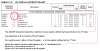
As per the attached picture, I pointed out in red cycle
that is Destination. so Destination can be W or F but in table sows only F
please guide me
Hi
happy New yea All.
As per the attached picture, I pointed out in red cycle
that is Destination. so Destination can be W or F but in table sows only F
please guide me
micropad...when executing a 2 operand instruction (i.e. most instructions that end with "wf" are 2 operand instructions), the second operand is the destination operand where the result of the instruction will get stored. There are only two choices for this...W or F.
If you use F, the result gets stored in the file location that the instruction was performed on.
If you use W, the result gets stored in the W register while the contents of the file that the instruction was performed on remains unchanged.
If you are using an assembler or a compiler you don't have to worry about the encoding. That is all taken care of for you.
In the ADDWF instruction, it starts 000111
The next bit is the destination, "d". It is either 0 representing a destination of the W register, or 1 representing a destination of the addressed register, F.
The last 7 bits, "fffffff", are the addressed register, F.
That is because d can be either W or F. You are confusing two different things together.
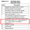
The f in your original picture (i.e. ADDWF f, d) is for the register (or file) that is going to be operated on and can be a value between 0 and 0x7F. The d is the destination, which can be 0 or 1. If it is 0 the result is stored back in W, if it is 1 the result is stored back to the register you oprate on (i.e. the 0 - 0x7F).
In the datasheet 'f' is used to describe two different things.
In the processor header w and f are defined to 0 and 1 respectively to make assembly writing easier. It's easier to see what "addwf porta, w" does as opposed to "addwf porta, 0".
Yes..."f" and "d" are variables that the data sheet uses for the purpose of illustrating the syntax of the instruction only. You would replace "f" with the file address that you wish for the instruction to be performed on, then replace the "d" with either W or F, depending on where you want it to store the result of the instruction.
That is because d can be either W or F. You are confusing two different things together.
The f in your original picture (i.e. ADDWF f, d) is for the register (or file) that is going to be operated on and can be a value between 0 and 0x7F. The d is the destination, which can be 0 or 1. If it is 0 the result is stored back in W, if it is 1 the result is stored back to the register you oprate on (i.e. the 0 - 0x7F).
In the datasheet 'f' is used to describe two different things.
In the processor header w and f are defined to 0 and 1 respectively to make assembly writing easier. It's easier to see what "addwf porta, w" does as opposed to "addwf porta, 0".
It looks like instruction ADDWF does not include the W register as a third operand in table 15-2 because the W register can be chosen as a destination by the second 'd' operand. If you are asking why the W register is not included as a source operand, I would guess that is because it is implied as a source operand in the instruction name itself, and it's address is already known. A more detailed description is shown in section 15.2.
This site uses cookies to help personalise content, tailor your experience and to keep you logged in if you register.
By continuing to use this site, you are consenting to our use of cookies.