Continue to Site

Welcome to our site!

Electro Tech is an online community (with over 170,000 members) who enjoy talking about and building electronic circuits, projects and gadgets. To participate you need to register. Registration is free. Click here to register now.

  • Welcome to our site! Electro Tech is an online community (with over 170,000 members) who enjoy talking about and building electronic circuits, projects and gadgets. To participate you need to register. Registration is free. Click here to register now.

Designing demodulator for diffenentially modulated signal.

Status
Not open for further replies.

Alex_bam

New Member
Hello,
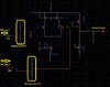
I am demodulating differential signal using LPF based demodulator. The schematic of the entire system is attached which includes diff modulator, coupling capacitors, and demodulator.
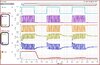
A modulated signal of 17 Mhz is demodulated. For the demodulator, I designed a 2-stage differential amplifier to amplify the diff signal then LPF is utilized to filter high frequencies, finally, the output signal is retrieved using Schmitt trigger. For LPF I used a single capacitor, the output impedance of 2-stage op-amp and capacitor constitute LPF.

Can anyone comment Why the designed 2 stage op-amp and LPF is not amplifying and filtering the modulated signal? According to my
understanding, the design op-amp parameters are adequate to demodulate the signal.

The design parameters of 2-stage op=amp are: ICMR+= 4V ICMR-=1.5V , GBW=40Mhz, Gain=68dB, Vdd=5V, C_load= 2pF.

Thanks.
 

Attachments

  • 20210709_192035 (1).jpg
    20210709_192035 (1).jpg
    352.7 KB · Views: 243
  • diff.JPG
    diff.JPG
    179.3 KB · Views: 245
  • diff1.JPG
    diff1.JPG
    288.6 KB · Views: 252
  • diff2.JPG
    diff2.JPG
    198.1 KB · Views: 245
There is no detector / rectifier in the block diagram to extract the modulation "envelope".

The opamp will be giving an AC signal out, which filters to the same as the DC bias level.
 
There is no detector / rectifier in the block diagram to extract the modulation "envelope".

The opamp will be giving an AC signal out, which filters to the same as the DC bias level.

Thanks for your response.
Actually, I am using FM for the modulation of message signals. NAND gate-based muti-vibrator is used as a differential modulator which only oscillates when the message signal is in logic '1'. In the opposite state, the circuit remains in no oscillation mode, making this modulator power efficient

I got the idea of this technique from the article: "Signal transmission for an isolated gate driver using capacitive coupling technique" in which Amplifier+LPF is utilized for demodulating single-ended Freq modulated message signal
 
NAND gate-based muti-vibrator is used as a differential modulator which only oscillates when the message signal is in logic '1'.

That's AM; carrier on or off (high or low amplitude), not FM where a carrier is always there but changed in frequency with the modulation.

The FM demod you mention sounds like a version of "Slope detection" - but it would still need an envelope detector, though in that case after the filter rather than before it.
 
actually this is "on-off keying" (OOK) and all you need is an envelope detector or envelope follower to detect this signal. in it's simplest form, all you need is a diode, resistor, and capacitor to regenerate the filtered envelope of the input signal, and a schmitt-trigger buffer to change it back to a logic signal.
 
Status
Not open for further replies.

Latest threads

New Articles From Microcontroller Tips

Back
Top