Continue to Site

Welcome to our site!

Electro Tech is an online community (with over 170,000 members) who enjoy talking about and building electronic circuits, projects and gadgets. To participate you need to register. Registration is free. Click here to register now.

  • Welcome to our site! Electro Tech is an online community (with over 170,000 members) who enjoy talking about and building electronic circuits, projects and gadgets. To participate you need to register. Registration is free. Click here to register now.

Design of a Bio-Feedback Device

Status
Not open for further replies.

Ravi

Member
Hi Friends, :)

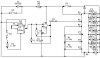
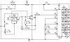
I intend to build a galvanic skin resistance bio-feedback device to indicate stress level in a person. The theory in my mind is to use a resistance bridge consisting of an electrodes, 1.5V battery, a fixed resistor and a potentiometer. When the electrodes are attached to the subject, the subject's resistance becomes part of the bridge and then the bridge could be balanced using the pot. The out put of the bridge is fed to the input of a op-amp which could be set up as a difference amplifier. (I want to use a high gain op-amp like CA3140 because that simlifies the power requirements). Once balanced, this amplifier will amplify any minor change in the subject's resistance.

I can feed the output of the op-amp to the input of a chip like LM3914 where it reads the voltage and converts it into a digital display using 10 LED's.

This is very straightforward but I was wondering whether this method is workable. I appreciate the views of every one or could anybody suggest a better method. The unit has to be portable and it should operate from a single ended +9 V power supply.

Thanks in advance
 
Thanks. However, the link does not give the infor.I'm looking for. The schematic is attached. The ckt is broken down into two main parts. The front end consists of the op-amp and resisitance bridge. This is the actual bio-feed back circuit. The back end of the circuit, the 3914 IC and ten LED's make up the display section. I would appreciate if any one tells me that this is a workable method.

Regards
 

Attachments

  • bio-feedback.jpg
    bio-feedback.jpg
    28.1 KB · Views: 2,364
Ravi, we have several bio feedback skin resistance machines here where I work. None of these uses a bridge type input. I think a bridge circuit is far too narrow in range for practical use. You would need several bridges, selected via a switch.
Skin resistance varies over a rather wide range between different persons and the equipment has to be balanced for whatever base resistance the subject has. Our machines have 3 switch ranges and a fine control pot to zero the meter needle at mid scale.
This is where your row of LED's will let you down unless you arrange them to read up AND down from a centre position, iow, two 3914's at least. A single one would need much too large steps to be useful and keep in range once the supject starts sweating, :wink: the smaller the steps the better the feedback. There is also a 'sensitivity' control on our units which does fine tune the meter's reaction to the input changes.
Regarding the electrodes, if you *must* use electrodes, the only types I found remotely useful are the rubberised black plastic ones as used with Tens machines. Any electrode designed for EMG, etc, does not work for this purpose in my experience.
For finger bio feedback, a Velcro strap collar with ss steel wool as contact material is easiest to use and works reliably.
Good luck
Klaus
 
Many thanks Klaus.So you suggest to use multiple bridges :?: If the bridge input method is not suitable, what would be an alternative.I would appreciate if you would give me a suitable schematic (if I''m not asking too much) or a link to obtain more details. With the ckt shown in my previous post, would it be possible to adjust the LED graph to lit midway by adjusting the balance pot. :?: Anyway I have not build this ckt yet.My point is that when you use this for relaxation and tension reduction, you will have to set the balance pot to light the LED graph in the upper portion. As you relax or reduce tension the body's resistance increases, which will be seen an gradual down ward sloping of the graph.right?When you reach the bottom you can adjust the balance pot to bring it back up and then try to bring it down again. I agree with you 'smaller the steps the better the feedback'. Thanks again for the suggestion regarding electrodes.
 
Hi Ravi,
I have in front of me the input circuit of a simple skin resistance biofeedback unit. Unfortunately, no means to send you a copy of this.
The electrode input goes staight (via 10k) to the negative input of an Op amp (LM324), the electrode common goes to a reference supply.
The Amp has a standard gain arrangement, consisting of a 3 pos switch and selectable gain resistor (10k, 100k, 1M).
This is followed by a second amplifier with a presettable gain (trimpot) and the balance control is a pot between these two amps.
There follow two more op amps for the 'mode' control (audible feedback) and a final amp with the gain pot adjusting sensitivity. The meter connects between the output of this amp and the reference.
The circuit runs of +-9V (pp3 batteries), the only unusual thing is the reference for the common which I think is to allow for changing battery voltages
I think your bridge idea would work but makes it a rather complex task to switch ranges. The above is much simpler.
You would look for an input from the finger electrodes in the range of 5k to perhaps 30k Ohms.
With regard to adjusting the balance, the less you have to fiddle with that, once you zeroed it, the better unless you have someone else adjusting it for you. If you do that yourself you'll find your deep relaxation is broken the instant you reach for the knob... :wink:
Klaus
 
Didn't the 'Christian Scentists' market something like this?
I think they called it an 'E-meter'

They claimed some success in relaxation techniques ...
 
Thanks everybody :) I opted to go for a bridge method because this could be use as a lie detector too. Perhas it is the most famous attribute of a this type of device.
 
Ravi, as shown, the 1.5v battery cannot supply current to your feedback resistor (R5), so your bridge won't work. Skin resistance variation might cause a slight change in the output due to amplification of the input offset voltage of the op amp, but this will be insignificant. To get this to work, you need to ground the negative terminal of the 1.5v battery, leave the + pin of the op amp connected to the junction of J1 and R4, but remove the ground connection from that node (I'm calling the negative supply rail ground).
 
Many thanks Ron for your ideas. I have modified the bridge section of my ckt according to what you have suggested and appreciate if you could see whether it is now in oder.

Although you have mentioned the amplification of the input offset voltage by the op-amp is insignificant,this worries me a little. However, accodring to the data sheet of 3140, this can be nulled by connecting a 10K pot. between terminal 1 & 5 and returning its wiper arm to terminal 4 (V-).Will this be OK?
 

Attachments

  • bio-feedback-modified_ckt.jpg
    bio-feedback-modified_ckt.jpg
    29 KB · Views: 1,835
If your switches are ganged, your new circuit will probably work OK. If you turn off only S2, you will get an output from your op amp. The modification below should solve that problem, it it indeed exists. I also added a 10k resistor so you can adjust the offset voltage. You can change the value of this resistor to vary the sensitivity of the circuit.
I haven't looked at the CA3140 datasheet, but the recommended offset circuit should work. It's a little tricky to adjust offset since you only have a single supply, but I think the following procedure will work:
Short the ring of the jack (+ pin of op amp) to the wiper of the pot. Turn on S2 and set the voltage at the wiper of the pot to about 1 volt above GND (doesn't have to be exact). Leave the tip of the jack as it is. With a DVM connected from the wiper of the pot to the output of the op amp, adjust the offset adjustment pot for a zero volt reading. This will mean that no current is flowing through the 2.2Meg feedback resistor, which means that there is no offset. Remove the short when the adjustment is finished.
I haven't looked at the LM3914 portion of the circuit yet.
 

Attachments

  • bio-feedback-modified_ckt.gif
    bio-feedback-modified_ckt.gif
    11.3 KB · Views: 1,707
Thanks Ron.Very much appreciated.
 
Hi Friends :)

I think the switch S1 is incorrectly placed in my schematic. It should be placed in the pin 9 of 3914 limb and not as shown in the ckt. Further, is it necessary to use current limiting resistor(s) to drive the LED's if operated in a bar mode:?: Since all anodes are in a common bus, how if I powered them via a zener :?: Appreciate your views.
 
design a biofeedback device

I ran across this post onine. I'm very interested in designing and manufacturing a heart rate variability device for my company. I don't know quite where to start. I have some old equipment that I have taken apart to look at the board schematics but it's def not a field i'm familiar with. any books or information anyone can recommend?
 
Status
Not open for further replies.

Latest threads

New Articles From Microcontroller Tips

Back
Top