Hi to all!
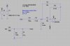
I'm designing a bandpass active filter stage using the MFB topology. You can see the schematic attached. The intended center frequency is 1.4kHz and the BW is between 1kHz and 2kHz.
The filter will have as input signal the output of an ADW22035 accelerometer.
Since it is my first active filter design and I'm generally new to electronics, I would like some help with the following:
1) Is the Cin AC coupling capacitor necessary? The signal coming from the accelerometer is already DC biased at 1.65V, however I was thinking that maybe the C1 and C2 capacitors are providing the necessary coupling.
2) How possible is the DC bias circuit (providing Vdd/2 to the non-inverting input) to interfere with filter and change its desired characteristics? I was thinking maybe to intercept an OpAmp buffer after the RC network. Just prefer to omit to save PCB space.
3) Is the polarity of the AC coupling capacitor correct or should be inverted? In fact, what is the criteria for determining the polarity?
4) Lastly, is a buffer between the accelerometer output and the filter necessary? Unfortunately, there is no information in the datasheet about the output impedance of the accelerometer. There is a 32kΩ series resistor at the output. Is this the output impedance? In that case the output impedance of the accelerometer and the input impedance of the filter are at the same magnitude. Is that ok?
As you can see, I have some pretty basic questions...
I would appreciate any help! Thanks in advance!