HelpingHand
New Member
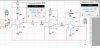
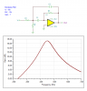
Design an Active Bandpass Filter
Center Frequency=50kHz
bandwidth of 10 kHz
passband gain 7
How would I complete a pencil and paper design and then simulate the design in Multisim.
After that I am to record my finding and data?? Confusing on how to start the design to begin with.
Center Frequency=50kHz
bandwidth of 10 kHz
passband gain 7
How would I complete a pencil and paper design and then simulate the design in Multisim.
After that I am to record my finding and data?? Confusing on how to start the design to begin with.

")
