Continue to Site

Welcome to our site!

Electro Tech is an online community (with over 170,000 members) who enjoy talking about and building electronic circuits, projects and gadgets. To participate you need to register. Registration is free. Click here to register now.

  • Welcome to our site! Electro Tech is an online community (with over 170,000 members) who enjoy talking about and building electronic circuits, projects and gadgets. To participate you need to register. Registration is free. Click here to register now.

Delco EST Ignition Wiring

Status
Not open for further replies.

wufibugs

New Member
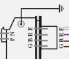
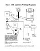
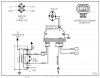
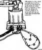
I was upgrading from points ignition on my boat to the EST pointless ignition. The EST distributor has two plugs, one from the coil and the other from the module, has 4 pins. The setup I got had the coil to distributor harness, but did not have the harness for the 4 pin male plug that goes to the HEI module. I got a standard 4 pin female harness. What I know is that in run mode, this plug only uses one wire/pin. In timing mode, it uses 3 wire/pins. The problem I'm having is which ones in each mode. The first diagram just shows how the pins/wires are labeled. I searched the internet and ultimately came up with a series of diagrams that seem to contradict one another. In the second diagram nothing is labeled, but the position of the wires makes it appear that in run mode the single wire used goes from module pin R to the shift interrupter. In timing mode, pin R is instead connected to a 12v source and the jumpered wires are pins G and B. The latter seems logical because in timing mode, the advance function is disabled by grounding via pin G. However the third diagram shows the wiring in reverse: in timing mode the jumpered wires are R and E, and the 12v source is B. In run mode, B would apparently be the wire to the shift interrupter [which happens to be white/green]. The fourth picture is of the EST distributor in timing mode and shows the jumpered wires in what appear to be the R & E location.
If any one can clarify this for me, I would be eternally, well at least grateful for life.
 

Attachments

  • Delco Est  8  pin module v 3.jpg
    Delco Est 8 pin module v 3.jpg
    20.6 KB · Views: 954
  • Wiring for Delco IL4EST v2.jpg
    Wiring for Delco IL4EST v2.jpg
    105.9 KB · Views: 2,370
  • EST Module Wiring Diagram.jpg
    EST Module Wiring Diagram.jpg
    158.5 KB · Views: 5,154
  • Wiring for Delco IL4EST v3.jpg
    Wiring for Delco IL4EST v3.jpg
    34.9 KB · Views: 990
Not sure about how it works with boat motors, but in car motors the timing advance comes from the ECM, not the coil. In the newer HEI distributors you jumper a wire to set initial timing, and then remove the jumper to let the ECM do it's thing and control the advance and retard as needed. Does the Mercruiser have an ECM?
 
No they usually do not and especially not the older ones. Since mine started life with points and, I think centrifugal advance, there was neither ECM nor PCM. As you can see b the drawings, timing is handled as you outline: by jumpering what I assume are the wires that would trigger advance. I assume spark advance in this system is handled by the distributor module.
Now that I think on it, I am wondering if the distributor module used EST systems in cars is different than the one used in the marine version and that explains what appears to be the two wiring configurations?
 
Until you posted this I never heard it called EST. The old HEI used both centrifical and vacuum advance. But the new style HEI I'm assuming what is similar to your EST uses signals from both a cam position sensor and a crank position sensor and vehicle speed sensor to the ECM and then send the correct signal to the distributor. The signal from the ECM is the ignition advance that is needed for all of the parameters set by the 3 sensors.

The jumper is to cut out all of the advances to set base timing, as soon as that is set the jumper is removed to allow the ECM to take over. Is there a Mercruiser forum you could ask about this? You may need more than just the distributor to make it work.
 
The setup I got was from a later model Mercruiser. These were factory installed on newer boats. There is no provision or wiring for an ECM or PCM that would provide the more extensive data cars use for their advance curves. I assume the marine version only relies on the RPM input it gets from the coil. The wire from the shift interrupter is only to momentarily kill the spark when going from forward to reverse to prevent transmission damage. I did post on a couple of boat forums but got no response. I also communicated with the person who actually drew the second diagram and clarified which pins to use. I followed those instructions but when I got no spark, I continued doing research and found the third diagram. This made me wonder which wiring scheme was correct. I also got a new distributor cap, rotor, high tension lead, and module just to make sure my no spark was not related to failing parts.
 
I have to wonder what is the reason to switch from standard HEI? I have no idea how the EST could work without it having a way to monitor the crank and cam positions. Speed yes, beacuse the VSS speed sensor takes the place of the vacuum advance, but normal timing, is a mystery to me as how they are doing it.

Did you also get the coil when you got the other parts? If so using it should make it work. Maybe it's time to get one of the Clymer manuals - https://www.clymer.com/s/mercruiser/marine-manuals
 
I did get the coil and the harness that goes from the coil to distributor. The original ignition was standard points/condenser with centrifugal advance and needed to be rebuilt. Turned out to be cheaper to upgrade to HEI, of which the Delco EST system is a variant. If it had HEI, I would have happily kept it.
I already have the shop manual for my boat which does have a wiring diagram for the later models that came with the EST system. Unfortunately, the diagram does not make it clear which pin on the module is active in run mode [ie which of the 4 pins/wires goes to the shift interrupter].
 
I'm sorry I wasn't of more help to you. Maybe one of these will show you what you need to know. This one was too large to post - **broken link removed**
 

Attachments

  • 36c97f52-be29-4a64-9ab5-8bf8b351bf86_Delco_EST.pdf
    315 KB · Views: 418
  • 90_15.pdf
    69.2 KB · Views: 339
  • 123-7878.pdf
    276.5 KB · Views: 314
Status
Not open for further replies.

Latest threads

New Articles From Microcontroller Tips

Back
Top