Continue to Site

Welcome to our site!

Electro Tech is an online community (with over 170,000 members) who enjoy talking about and building electronic circuits, projects and gadgets. To participate you need to register. Registration is free. Click here to register now.

  • Welcome to our site! Electro Tech is an online community (with over 170,000 members) who enjoy talking about and building electronic circuits, projects and gadgets. To participate you need to register. Registration is free. Click here to register now.

Decoding IR Control

Status
Not open for further replies.

AtomSoft

Well-Known Member
I have a cable TV remote and cant find any information on it online about the IR protocol used. I want to make my own remote soon and would love to learn this protocol.

CHAN 1 BTN: 1101100001000100111101
CHAN 2 BTN: 1101110001000100011101
CH UP BTN: 1101110111000100010001

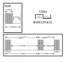
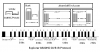
I hand decoded the bits, or i think i did at least. Can someone help me identify how its used? Like can someone tell me what the parts might be..

I tested a ton of buttons and most if not all start with 1101 ... so i assume thats like a DEVICE ID... If i break it up into parts it looks like

CHN 1 BTN: 1101-1000-0100-0100-1111-01
CHN 2 BTN: 1101-1100-0100-0100-0111-01
CHN UP BTN: 1101-1101-1100-0100-0100-01

But im not sure if thats the case or:


CHAN 1 BTN: 11011-00001-00010-01111-01
CHAN 2 BTN: 11011-10001-00010-00111-01
CH UP BTN: 11011-10111-00010-00100-01

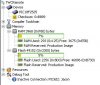
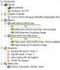
See my issue? I know there is a start pulse also i the front... Anyway here is a Logic saved file...

The logic software is free so you can inspect my findings... Thanks for the help in advance. Any code created will be shared in this post and my site.
 

Attachments

  • IR.zip
    852 bytes · Views: 490
Ok ive been thinking i checked chan 3 btn also:

1: 11011 0000 1000100 1111 01
2: 11011 1000 1000100 0111 01
3: 11011 0100 1000100 1011 01

Looks like :
first 5 bits are the same (DEVICE?)
next 4 are possibly commands? in LSb form
Next 7 are?
next 4 are inverse of command perhaps...
last 2 are?
 
Ok further into it now:

Code:
  01> 11011 0000 1000100 1111 01
  02> 11011 1000 1000100 0111 01
  03> 11011 0100 1000100 1011 01
  04> 11011 1100 1000100 0011 01
  05> 11011 0010 1000100 1101 01
  Up> 11011 1011 1000100 0100 01
Play> 11011 1100 1100100 0011 00
Stop> 11011 0010 1100100 1101 00

First 5 bits must be like some sync i guess
Next 4 bits must be the command
Next 7 bits must be a some sync or something
Next 4 bits must be the inverse of command
Next 2 bits are Device... 01 = TV, 00 = DVR

(im using a Time Warner Cable Box Remote (UR5U-8780L-TWY))

As you can see the command is like SIRC kind of... Button 1 is 0x00, Button 2 is 0x1, Button 3 is 0x2 etc... so there is something similar going on here.... Im tired and will scan more numbers and try to make more sense of this after a break :)
 
Last edited:
Further study makes me think its like:

Code:
  01> 11011 0000 10 00100 1111 01
  02> 11011 1000 10 00100 0111 01
  03> 11011 0100 10 00100 1011 01
  04> 11011 1100 10 00100 0011 01
  05> 11011 0010 10 00100 1101 01
  00> 11011 1001 10 00100 0110 01
ChUp> 11011 1011 10 00100 0100 01
ChDn> 11011 0111 10 00100 1000 01
Play> 11011 1100 11 00100 0011 00
Stop> 11011 0010 11 00100 1101 00
Down> 11011 1101 00 00100 0010 11
  Up> 11011 0100 00 00100 1011 11
Left> 11011 1100 00 00100 0011 11

First 5 = SYNC
NEXT 4 = COMMAND
NEXT 2 = DEVICE
NEXT 5 = SYNC INVERTED
NEXT 4 = COMMAND INVERTED
NEXT 2 = DEVICE INVERTED
 
Last edited:
That would be... 16 Commands per device...with 4 device max... which would mean 64 buttons max for Actual Cable box usage... This is all theory but seems to be making more sense heh

START = 3.3ms LOW then 3.3ms HIGH
A LOGIC 1 = 900us LOW then 2.4ms HIGH
A LOGIC 0 = 900us LOW then 700us HIGH


Ill try to make a decoder with a PIC micro and some fancy UART code to see if i can read it easier :)
 
Awesome!! Got it i think... This is the results from a test using a PIC18F2525 and CP2102 for USB to UART stuff.. Using CoolTerm(terminal)

Code:
AtomSoftTech IR Decoder Test
Ready for input...

Sync = 27, Command = 00, Device = 01, Inv. Sync = 04, Inv. Command = 15, Inv.  Device = 02 
Sync = 27, Command = 01, Device = 01, Inv. Sync = 04, Inv. Command = 14, Inv.  Device = 02 
Sync = 27, Command = 02, Device = 01, Inv. Sync = 04, Inv. Command = 13, Inv.  Device = 02 
Sync = 27, Command = 03, Device = 01, Inv. Sync = 04, Inv. Command = 12, Inv.  Device = 02

Buttons 1,2,3 and 4
 
Last edited:
Here is the code if anyone is interested in it:

Code:
/*------------------------
Author: Jason Lopez
Company: AtomSoftTech.com
IDE: MPLABX, COMPILER = C18
MCU = PIC18F2525

Info: Time Warner Cable - Remote (UR5U-8780L-TWY) Decoder.
Protocol: Unknown...(somewhat like NEC) SYNC, COMMAND, DEVICE, !SYNC, !COMMAND, !DEVICE
--------------------------*/
#include <p18f2525.h>
#include <delays.h>
#include <string.h>

#pragma config WDT = OFF, LVP = OFF, OSC = INTIO67, XINST = OFF

/************************************
Prototypes
*************************************/
void main(void);
void init_uart(void);
void UartByte(char byte);
void UartStr(rom char *string);
void DecodeTWC(void);

/************************************
 Global Variables and Definitions
*************************************/
#define INPUT 1
#define OUTPUT 0

#define D600US() Delay100TCYx(13)
#define D1MS() Delay100TCYx(20)
#define D1P8MS() Delay100TCYx(36)

#define IR PORTBbits.RB0
#define IR_DDR TRISBbits.TRISB0

#define RSYNC 0x1B
#define NSYNC 0x04

char SyncTmp = 0;
char CmdIn = 0;
char DevIn = 0;
char bytes[6]={0};

void main(void)
{
    char x;
    OSCCON = 0x72;      	//8MHz clock
    while(!OSCCONbits.IOFS);	//wait for osc stable

    ADCON1 = 0x0F;              //All pins digital
    init_uart();                //Init the UART

    IR_DDR = INPUT;             //IR Direction is Input

    UartStr((rom char*)"AtomSoftTech IR Decoder Test\n");
    UartStr((rom char*)"Ready for input...\n\n");
    
    while(1)
    {
        for(x=0;x<6;x++)
            bytes[x] = 0;
        
        DecodeTWC();
        UartStr((rom char*)"Sync = ");
        UartByte(((bytes[0] / 10)+0x30)); UartByte(((bytes[0] % 10)+0x30));
        UartStr((rom char*)", Command = ");
        UartByte(((bytes[1] / 10)+0x30)); UartByte(((bytes[1] % 10)+0x30));
        UartStr((rom char*)", Device = ");
        UartByte(((bytes[2] / 10)+0x30)); UartByte(((bytes[2] % 10)+0x30));

        UartStr((rom char*)", Inv. Sync = ");
        UartByte(((bytes[3] / 10)+0x30)); UartByte(((bytes[3] % 10)+0x30));
        UartStr((rom char*)", Inv. Command = ");
        UartByte(((bytes[4] / 10)+0x30)); UartByte(((bytes[4] % 10)+0x30));
        UartStr((rom char*)", Inv.  Device = ");
        UartByte(((bytes[5] / 10)+0x30)); UartByte(((bytes[5] % 10)+0x30));

        UartStr((rom char*)" \n");
    }
}

void init_uart(void){
    TRISC  = 0b10000000;
    TXSTAbits.SYNC = 0;
    BAUDCTLbits.BRG16 = 0;
    TXSTAbits.BRGH = 1;
    SPBRG = 51;        //9600bps for 8 Mhz

    RCONbits.IPEN = 1;
    IPR1bits.RCIP = 1; //PRIORITY

    TXSTAbits.TXEN = 1;  //ENABLE TX
    RCSTAbits.CREN = 1;  //ENABLE RX
    RCSTAbits.SPEN = 1;  //ENABLE SERIAL PORT and PIN Config

    PIE1bits.RCIE = 0;   //DISABLE RX Interrupt
    PIR1   = 0b00000000;
    PIE1   = 0b00101000;
    IPR1   = 0b00101000;
    INTCON = 0b11000000;

    Delay10TCYx(100);
}
void UartByte(char byte){
    while(!PIR1bits.TXIF)     //wait until TXIF is high
        continue;
    TXREG = byte;    //put byte into Transmit Register
}
void UartStr(rom char *string){
    while(*string)
    {
        while(!PIR1bits.TXIF)     //wait until TXIF is high
            continue;
        TXREG = *string++;    //put byte into Transmit Register
    }
}
void DecodeTWC(void){

    char x;
    char curByte = 0;

    while(IR == 1);     //Waiting For Start...
    while(IR == 0);     //Waiting For Start to go High...
    while(IR == 1);     //Waiting For Start to go Low...

    for(x=0;x<5;x++ )
    {
        bytes[curByte] >>= 1;
        while(IR == 0);
        D600US();
        if(IR == 1)
            bytes[curByte] |= 0x10;
        D600US();
        if(IR == 0)
        {
            bytes[curByte] &= 0x0F;
        }
        else
        {
            D600US();D600US();D600US();
        }
    }
    curByte++;
    for(x=0;x<4;x++ )
    {
        bytes[curByte] >>= 1;
        while(IR == 0);
        D600US();
        if(IR == 1)
            bytes[curByte] |= 0x08;
        D600US();
        if(IR == 0)
        {
            bytes[curByte] &= 0x07;
        }
        else
        {
            D600US();D600US();D600US();
        }
    }
    curByte++;
    for(x=0;x<2;x++ )
    {
        bytes[curByte] >>= 1;
        while(IR == 0);
        D600US();
        if(IR == 1)
            bytes[curByte] |= 0x02;
        D600US();
        if(IR == 0)
        {
            bytes[curByte] &= 0x01;
        }
        else
        {
            D600US();D600US();D600US();
        }
    }
    curByte++;
    for(x=0;x<5;x++ )
    {
        bytes[curByte] >>= 1;
        while(IR == 0);
        D600US();
        if(IR == 1)
            bytes[curByte] |= 0x10;
        D600US();
        if(IR == 0)
        {
            bytes[curByte] &= 0x0F;
        }
        else
        {
            D600US();D600US();D600US();
        }
    }
    curByte++;
    for(x=0;x<4;x++ )
    {
        bytes[curByte] >>= 1;
        while(IR == 0);
        D600US();
        if(IR == 1)
            bytes[curByte] |= 0x08;
        D600US();
        if(IR == 0)
        {
            bytes[curByte] &= 0x07;
        }
        else
        {
            D600US();D600US();D600US();
        }
    }
    curByte++;
    for(x=0;x<2;x++ )
    {
        bytes[curByte] >>= 1;
        while(IR == 0);
        D600US();
        if(IR == 1)
            bytes[curByte] |= 0x02;
        D600US();
        if(IR == 0)
        {
            bytes[curByte] &= 0x01;
        }
        else
        {
            D600US();D600US();D600US();
        }
    }
    
    CmdIn = bytes[1];
    DevIn = bytes[2];

    Delay1KTCYx(100);
}
Its kind of like a NEC protocol but with some differences.

Space... Can be made less but heh im tired from the hard work :)
twcspace-jpg.59465
 

Attachments

  • twcspace.jpg
    twcspace.jpg
    24.7 KB · Views: 2,627
Last edited:
Smaller Flash usage: (Saved 728 bytes)
Code:
/*------------------------
Author: Jason Lopez
Company: AtomSoftTech.com
IDE: MPLABX, COMPILER = C18
MCU = PIC18F2525

Info: Time Warner Cable - Remote (UR5U-8780L-TWY) Decoder.
Protocol: Unknown...(somewhat like NEC) SYNC, COMMAND, DEVICE, !SYNC, !COMMAND, !DEVICE
--------------------------*/
#include <p18f2525.h>
#include <delays.h>
#include <string.h>

#pragma config WDT = OFF, LVP = OFF, OSC = INTIO67, XINST = OFF

/************************************
Prototypes
*************************************/
void main(void);
void init_uart(void);
void UartByte(char byte);
void UartStr(rom char *string);
void DecodeTWC(void);
char GetData (char bits);
/************************************
 Global Variables and Definitions
*************************************/
#define INPUT 1
#define OUTPUT 0

#define D600US() Delay100TCYx(13)
#define D1MS() Delay100TCYx(20)
#define D1P8MS() Delay100TCYx(36)

#define IR PORTBbits.RB0
#define IR_DDR TRISBbits.TRISB0

#define RSYNC 0x1B
#define NSYNC 0x04

char SyncTmp = 0;
char CmdIn = 0;
char DevIn = 0;
char bytes[6]={0};

void main(void)
{
    char x;
    OSCCON = 0x72;      	//8MHz clock
    while(!OSCCONbits.IOFS);	//wait for osc stable

    ADCON1 = 0x0F;              //All pins digital
    init_uart();                //Init the UART

    IR_DDR = INPUT;             //IR Direction is Input

    UartStr((rom char*)"AtomSoftTech IR Decoder Test\n");
    UartStr((rom char*)"Ready for input...\n\n");
    
    while(1)
    {
        for(x=0;x<6;x++)
            bytes[x] = 0;
        
        DecodeTWC();
        UartStr((rom char*)"Sync = ");
        UartByte(((bytes[0] / 10)+0x30)); UartByte(((bytes[0] % 10)+0x30));
        UartStr((rom char*)", Command = ");
        UartByte(((bytes[1] / 10)+0x30)); UartByte(((bytes[1] % 10)+0x30));
        UartStr((rom char*)", Device = ");
        UartByte(((bytes[2] / 10)+0x30)); UartByte(((bytes[2] % 10)+0x30));

        UartStr((rom char*)", Inv. Sync = ");
        UartByte(((bytes[3] / 10)+0x30)); UartByte(((bytes[3] % 10)+0x30));
        UartStr((rom char*)", Inv. Command = ");
        UartByte(((bytes[4] / 10)+0x30)); UartByte(((bytes[4] % 10)+0x30));
        UartStr((rom char*)", Inv.  Device = ");
        UartByte(((bytes[5] / 10)+0x30)); UartByte(((bytes[5] % 10)+0x30));

        UartStr((rom char*)" \n");
    }
}

void init_uart(void){
    TRISC  = 0b10000000;
    TXSTAbits.SYNC = 0;
    BAUDCTLbits.BRG16 = 0;
    TXSTAbits.BRGH = 1;
    SPBRG = 51;        //9600bps for 8 Mhz

    RCONbits.IPEN = 1;
    IPR1bits.RCIP = 1; //PRIORITY

    TXSTAbits.TXEN = 1;  //ENABLE TX
    RCSTAbits.CREN = 1;  //ENABLE RX
    RCSTAbits.SPEN = 1;  //ENABLE SERIAL PORT and PIN Config

    PIE1bits.RCIE = 0;   //DISABLE RX Interrupt
    PIR1   = 0b00000000;
    PIE1   = 0b00101000;
    IPR1   = 0b00101000;
    INTCON = 0b11000000;

    Delay10TCYx(100);
}
void UartByte(char byte){
    while(!PIR1bits.TXIF)     //wait until TXIF is high
        continue;
    TXREG = byte;    //put byte into Transmit Register
}
void UartStr(rom char *string){
    while(*string)
    {
        while(!PIR1bits.TXIF)     //wait until TXIF is high
            continue;
        TXREG = *string++;    //put byte into Transmit Register
    }
}
void DecodeTWC(void){

    char x;
    char curByte = 0;

    while(IR == 1);     //Waiting For Start...
    while(IR == 0);     //Waiting For Start to go High...
    while(IR == 1);     //Waiting For Start to go Low...

    bytes[0] = GetData(5);
    bytes[1] = GetData(4);
    bytes[2] = GetData(2);
    bytes[3] = GetData(5);
    bytes[4] = GetData(4);
    bytes[5] = GetData(2);

    Delay1KTCYx(100);
}

char GetData (char bits){
    char x;
    char data=0;

    for(x=0;x<bits;x++ )
    {
        data >>= 1;
        while(IR == 0);
        D600US();
        if(IR == 1)
            data |= (1<<(bits-1));
        D600US();
        if(IR == 0)
        {
            data &= ~(1<<(bits-1));
        }
        else
        {
            D600US();D600US();D600US();
        }
    }

    return data;
}

twcspace2-jpg.59469
 

Attachments

  • twcspace2.jpg
    twcspace2.jpg
    33 KB · Views: 2,088
Last edited:
Further study makes me think its like:

Code:
  01> 11011 0000 10 00100 1111 01
  02> 11011 1000 10 00100 0111 01
  03> 11011 0100 10 00100 1011 01
  04> 11011 1100 10 00100 0011 01
  05> 11011 0010 10 00100 1101 01
  00> 11011 1001 10 00100 0110 01
ChUp> 11011 1011 10 00100 0100 01
ChDn> 11011 0111 10 00100 1000 01
Play> 11011 1100 11 00100 0011 00
Stop> 11011 0010 11 00100 1101 00
Down> 11011 1101 00 00100 0010 11
  Up> 11011 0100 00 00100 1011 11
Left> 11011 1100 00 00100 0011 11
...

Nicely done Atomsoft! :) I was watching that pattern emerge as you made each post.
 
Last edited:
Ok i think its complete... should be able to make a remote with this info now... :)

ir-png.59487
 

Attachments

  • IR.png
    IR.png
    13.5 KB · Views: 2,126
Last edited:
Status
Not open for further replies.

Latest threads

New Articles From Microcontroller Tips

Back
Top