Continue to Site

Welcome to our site!

Electro Tech is an online community (with over 170,000 members) who enjoy talking about and building electronic circuits, projects and gadgets. To participate you need to register. Registration is free. Click here to register now.

  • Welcome to our site! Electro Tech is an online community (with over 170,000 members) who enjoy talking about and building electronic circuits, projects and gadgets. To participate you need to register. Registration is free. Click here to register now.

DCF77 antenna - DIY

Status
Not open for further replies.
Unfortunatelly, DCF77 module cost more than GPS module here... As GPS module does not really work inside building, I'm trying to make my own DCF77 module with hand made antenna to acquire precise time.

Currently I have no oscilloscope nor LC meter, just frequency counter. That should be sufficient...

I have actually wired antenna from 0.2mm magnet wire and some unknown iron rod possibly salvaged from some old AM radio.

The rod is around 5cm long and have diameter around 0.5 cm.

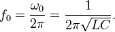
The antenna should have around 5mH and 1000pF (5% MKT) in parallel LC tank basic circuit should be sufficient to tune desire 77.5KHz, decreasing or increasing number of turns. It is impossible to make any reasonable calculation for number of turns since composition of the rod is unknown.

If measure frequency with this simple LC tank circuit, would it be necessary some protective measure or it is simply enoug applying regulated 3.3V or 5V directly in order to provide accurate reading?

Thanks.
 
Last edited:
If measure frequency with this simple LC tank circuit, would it be necessary some protective measure or it is simply enoug applying regulated 3.3V or 5V directly in order to provide accurate reading?

To get a reading with a frequency counter you would need to make an oscillator, utilising the tuned circuit as the tuned element of the oscillator - you might also need a buffer stage to feed the counter.
 
Last edited by a moderator:
To get a reading with a frequency counter you would need to make an oscillator, utilising the tuned circuit as the tuned element of the oscillator - you might also need a buffer stage to feed the counter.

Not sure I have understood, nor that I have explained well...

This is similar frequency counter, made by Arduino. Preamp stage is 74HC14 or transistor based circuit.
**broken link removed**

Preamp (two possible variations):
**broken link removed**
The simplest LC tank:
220px-Parallel_LC_Circuit.svg.png
4649ce6f1aa676a20ef8e19ba16d4b25.png


Applying voltage to LC tank circuit, it will start to resonate, then preamp input is connected with...
By known formula, it is easy to calculate that freq. need to be 71176Hz, assuming capacitance is exactly 1000pF.

My question was: what is necessary additionally on the upper LC tank circuit in order to get proper resonant circuit before input to the preamp stage in order to get precise reading? Some resistors, diode, opamp...?

In this stage I just need to be sure inductance is near to 5mH, not to listen nor decode signal from the DCF77 station itself.

Thanks and sorry if maybe I was unclear a bit.
 
Last edited:
Applying voltage to LC tank circuit, it will start to resonate
No it will not.

Too much text book theory. Applying a pulse to a tuned circuit will make the tuned circuit ring like a bell.
This does not form a sensible basis for measuring the resonant frequency of the LC circuit in any practical application.

Either use a test oscillator to excite your tuned circuit and measure the response with an RF voltmeter or 'scope.
Or, make an oscillator circuit and use your tuned circuit in that oscillator.

JimB
 
Why not just Google "DCF77 receiver" There are lots of circuits and description of decoding the signal.

Les.
 
Why not just Google "DCF77 receiver" There are lots of circuits and description of decoding the signal.

Les.

I do not need anything else, already collected all related with receiving and decoding the signal...

At this stage I have only to wire rod properly and blindly to make it around 5mH, with frequency counter only.

Thanks anyway.
 
Last edited:
Either use a test oscillator to excite your tuned circuit and measure the response with an RF voltmeter or 'scope.
Or, make an oscillator circuit and use your tuned circuit in that oscillator.

As already wrote, I have nothing else than plain frequency counter.
Pointer to a suitable oscillator circuit is answer I'm hoped to...

Thanks.
 
Pointer to a suitable oscillator circuit is answer I'm hoped to...

OK, no problem, try this:


Test  Oscillator.jpg

A simple circuit with a high input impedance which will not load the tuned circuit under test.

For a low frequency like 77kHz, make C2 about 100pF and RFC about 2 or 3 mH.

I have used this circuit a few times, but not recently.

JimB
 
Attempt is made to test this with LTSpice - failed. It started some oscillation, however it is unstable.

Probably my fault somewhere in construction or settings.
Two IRFZ44 are used in schematic, since this is free version.

I will try to make some cheap MCU based LC meter instead, complexity of the circuit is not too different than this. I'm quite sure there is not a single one comparator IC available in my junk box, as mentioned LM311.

Thanks.
 

Attachments

  • LC tank oscillator.asc
    1.9 KB · Views: 317
Hmmm....

IRFZ44 is a thundering great power MOSFET.

2N3819 is a small signal high frequency N channel junction FET.

Quite a difference, may account for why it will not work.

JimB
 
2N3819 is not available in LTspice free version.
IRFZ44 is just last tested. The same or similar behavior with other tested as well.

Never mind actually, I will try to make LC meter in the near future.
Thanks.
 
hi,
Open: C:\Program Files\LTC\LTspiceIV\lib\cmp [ your folder tree maybe different, but lib\cmp is the destination folder]
Find standard.jft folder. rename to standardjft.bak

Download the attached standard.txt file rename to standard.jft [ this is because the Site software will not allow .jft extensions]
Move this standard.jft to the C:\Program Files\LTC\LTspiceIV\lib\cmp

This will give you lots of nJfet models.

Section#3:
On your LTS circuit, use F2, then select the njf model, when the symbol appears on your circuit, right click on it, then select Pick New FET,
The 2N3819 should be there.

E
EDIT: try section #3 actions first, the 2N3819 may already be available.
 

Attachments

  • standard.txt
    23.3 KB · Views: 325
Hi testmpc,
If you want to build a cheap tester that measures capacity and inductance The component tester by "Banggood" that Nigel Goodwin mentioned in this thread
https://www.electro-tech-online.com/threads/esr-meter-diy.145392/#post-1228866
is worth considering. I ordered the kit this week and it arrived in about 3 days. Although it does not claim to be very accurate measuring inductance I measured an inductor of about 5 mH and the reading was better than 5% accuracy. I think the kit costs less than it would to buy the components. It cost me £9.22 ordered from their EU warehouse. (It is slightly cheaper ordered from China.)
This is the device on their website. https://www.banggood.com/DIY-Meter-...ESR-Inductance-Resistor-NPN-PNP-p-929603.html

Les.
 
I do not want to buy anything I can make myself! :)
To hobbyist, making simple devices gave some satisfactory and spare from lost of time and money...

Already made my own basic version and actually works suprisingly accurate measuring inductance. Capacitance is as well very accurate up to 100nF, however improving this is not of interest to me...

Rod is wired accordingly to reading as well module and device itself, working as intended.
Now, the last step is to make PCB and that should last an hour at least...

Thanks to anyone participated in this thread.
 
Status
Not open for further replies.

Latest threads

New Articles From Microcontroller Tips

Back
Top