Hello, All!
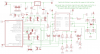
I would like to make a very simple DCC system (digital modell railway) with 16F716 commander and 16F716 decoder in engine.
I made electronics succesfully, when I apprehended using of booster, and logic of NMRA standard signal (preamble,0, address,0,instruction,0,error,1); but I don't know, how I get sended signals with decoder?
So; the logical 0 means that You change by booster "direction" of rails (change polarity) at first +/-, wait 58 mikrosec (using by 4 MHz xtal oscillator it means 58 steps), change polarity -/+, wait 58 mikrosec again, and sign is ready. Logical 1 is same, but the waiting time is 100 mikrosec.
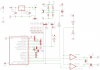
I tryed to simulate a signal-sending-routine: made a transmitter PIC and a receiver PIC. Both are same, difference is only that transmitter gives a logical 0 sign, receiver gets it.
I made a short bit-examination (receiver input is RB4):
btfss PORTB,4
goto $-1
wait_40mks
btfss PORTB,4
goto $-1
bsf PORTB,7 (connected LED)
I thought that if I sent a 58 mikrosec long sign (simulated BSF), if the 40 mks delay expired, the input sign 1 yet, that the second bit-trap enables to pass-on. If I put into routine a 100 mikrosec long delay, when it stops, the input sign must be ZERO (it expired before 42 mikrosecs...), the second bit trap must makes a never-ending cycle - BUT NOT !!!!!!!!!! NOT MAKES! WHY??????????????????????????????????
Please help me. What is the problem? What I corrupt? Please help me, If I shall understand it, I shall can make routines for my DCC system.
ThanX forwardly all helps!
fejesg
I would like to make a very simple DCC system (digital modell railway) with 16F716 commander and 16F716 decoder in engine.
I made electronics succesfully, when I apprehended using of booster, and logic of NMRA standard signal (preamble,0, address,0,instruction,0,error,1); but I don't know, how I get sended signals with decoder?
So; the logical 0 means that You change by booster "direction" of rails (change polarity) at first +/-, wait 58 mikrosec (using by 4 MHz xtal oscillator it means 58 steps), change polarity -/+, wait 58 mikrosec again, and sign is ready. Logical 1 is same, but the waiting time is 100 mikrosec.
I tryed to simulate a signal-sending-routine: made a transmitter PIC and a receiver PIC. Both are same, difference is only that transmitter gives a logical 0 sign, receiver gets it.
I made a short bit-examination (receiver input is RB4):
btfss PORTB,4
goto $-1
wait_40mks
btfss PORTB,4
goto $-1
bsf PORTB,7 (connected LED)
I thought that if I sent a 58 mikrosec long sign (simulated BSF), if the 40 mks delay expired, the input sign 1 yet, that the second bit-trap enables to pass-on. If I put into routine a 100 mikrosec long delay, when it stops, the input sign must be ZERO (it expired before 42 mikrosecs...), the second bit trap must makes a never-ending cycle - BUT NOT !!!!!!!!!! NOT MAKES! WHY??????????????????????????????????
Please help me. What is the problem? What I corrupt? Please help me, If I shall understand it, I shall can make routines for my DCC system.
ThanX forwardly all helps!
fejesg