Continue to Site

Welcome to our site!

Electro Tech is an online community (with over 170,000 members) who enjoy talking about and building electronic circuits, projects and gadgets. To participate you need to register. Registration is free. Click here to register now.

  • Welcome to our site! Electro Tech is an online community (with over 170,000 members) who enjoy talking about and building electronic circuits, projects and gadgets. To participate you need to register. Registration is free. Click here to register now.

DC to AC inverter

Status
Not open for further replies.

chopper

New Member
Hi everyone, i saw this circuit in some website and i would like to ask how the signal of the 555 timer can come out with a negative cycle in the following inverter?(since i know 555 timer only gives 0 to positive number )

is it because of the pnp transistor?when the 555timer gives 0 to the base of pnp transistor a negative cycle is created?
 

Attachments

  • 20082365544_DC to AC Inverter.JPG
    20082365544_DC to AC Inverter.JPG
    82.7 KB · Views: 16,645
The 555 does not produce a negative cycle. The 555 output switches from 0V to +12V just like you understood. The PNP and NPN are in voltage follower (look up common collector) mode, and with some losses also switch between 0V and +12V. The capacitor C8 provides only the alternating part of the voltage to the transformer.
 
Last edited:
mneary thanks for your reply,so this means the output has a positive and negative cycle is because of the capacitor c8?
 
No chopper, it doesn't have a negative cycle, it simply switches between 0 and 12 volts. The output is isolated because it goes through a transformer so you can have either a positive or negative output volts by simply supply the appropriate ground reference.
 
im sorry i still don get it,can you please explain to me how the output of the transformer will have a signal of positive and negative cycle ?
 
Because the transformers secondary is electrically isolated from it's primary it's been deferenced from ground.
 
A long time ago I analyzed the circuit. It has so many voltage losses that its output voltage is almost nothing when driving a load and is much too high without a load.

The inductor would need to be huge (and have a very high loss) to make the output a sine-wave at the mains frequency.
 
The circuit has too many voltage losses to work properly. The output voltage will be too low when loaded and will be too high without a load.

The inductor is much too small to filter the square-wave into a sine-wave.
It was copied from here:
 

Attachments

  • 555 inverter.PNG
    555 inverter.PNG
    12.4 KB · Views: 2,488
can you tell me whether the input of the primary transformer has a sinewave with positive and negative cycle ?

cause im still not too sure how a positive and negative cycle can appear at the secondary of the transformer although Sceadwian already explained earlier.
 
If that circuit works it may start out with 240 volts at its output but it will probibly be down to around 120 volts at a 2 watt load! :(
 
The 1uH inductor is much too small to filter the output square-wave into a sine-wave at the low frequency of the mains.

The output of a transformer is AC. AC has a positive half-cycle and a negative half-cycle.
 
The input to the transformer is not AC it is pulsed DC. Therefore it will give out a very ragged AC voltage. However with reference to the 555's 0v line the voltage will be AC above 0v. in other words with reference to the 555's 0v line the AC will always be positive.
 
Hi chopper,


The circuit works as follows...


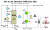
Before the circuit is turned on, the capacitor C8 is discharged.
When the circuit is first turned on, the output is low and because C8 is discharged
nothing much happens. Soon the output switches high, which drives Q3 into
conduction. As Q3 conducts it's emitter voltage rises fairly fast and this means
C8 (+) terminal rises fast, and because it rises fast C8 (-) terminal also rises
quite quickly, which puts a positive pulse at the upper primary lead of the output
transformer TR1. That's basically how it gets it's positive pulse, but now something
else starts to happen...
The pulse stays high for a while, and so current flows through C8 into TR1 primary,
which means C8 starts to charge up with it's (+) lead positive and it's (-) lead
negative. All the while the pulse is high some voltage appears across the transformer
primary and some begins to appear across the cap because it charges up somewhat.

Next the output of the 555 goes low, which starts the negative half cycle.
With the 555 output low and C8 having a positive voltage at it's (+) terminal,
Q4 begins to conduct emitter to collector, and that puts the (+) terminal of
C8 at approximately ground potential (close to 0v). With C8 (+) terminal now
at ground and we know that C8 was charged somewhat, that means that the
(-) terminal of C8 now has a negative voltage with respect to ground.
That negative voltage appears at the output transformer's primary, and since
the other lead is still connected to ground that means it now has a negative
voltage across it's primary.

Thus, the cycle started with a positive voltage across the primary and later
a negative voltage across the primary and that's basically how it gets both
positive and negative voltages across the primary.

The cap stores charge in the form of a voltage so it subtracts from the output
of the 555 and that's how the primary can go negative.


Another way to understand the basic operation is to replace C8 with a small battery
of maybe 1/2 the supply voltage and then observe how the primary goes negative
when the output of the 555 goes to zero and the PNP conducts. The positive
terminal of the battery would be forced to ground, so the negative terminal would
of course be negative with respect to ground so again the transformer gets it's
negative pulse that way.
 
Last edited:
The input to the transformer is not AC it is pulsed DC. Therefore it will give out a very ragged AC voltage. However with reference to the 555's 0v line the voltage will be AC above 0v. in other words with reference to the 555's 0v line the AC will always be positive.
I guess you didn't notice the capacitor C8.

The transformer receives a DC current briefly while C8 charges to Vcc/2, then it receives AC.
 
Status
Not open for further replies.

Latest threads

New Articles From Microcontroller Tips

Back
Top