Continue to Site

Welcome to our site!

Electro Tech is an online community (with over 170,000 members) who enjoy talking about and building electronic circuits, projects and gadgets. To participate you need to register. Registration is free. Click here to register now.

  • Welcome to our site! Electro Tech is an online community (with over 170,000 members) who enjoy talking about and building electronic circuits, projects and gadgets. To participate you need to register. Registration is free. Click here to register now.

DC power supply changes

Status
Not open for further replies.
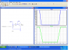
To eliminate the 'messy' turn-off entirely and have a snap-action turn-off instead (which might make the AVR happier), a bit of positive feedback can be applied with a third transistor and a second cap :-

Power Supply 12mod3.gif

In this circuit the second 100k resistor is unnecessary. When T2 starts to turn off, the rise of J3-4 is coupled through the 10nF cap to turn on T3 and so short the 10uF cap to ground, thus turning T2 fully off rapidly. The 1N4148 provides a path for the 10nF recharge current.
The alarm trip delay here is ~4 secs, i.e. is ~ 0.4*C, where C is in microfarads (assuming R=100k and the AVR pull-up = 10k).
 
Last edited:
There may be one other problem. When the 12 volts is missing or low the base emitter junction of the pnp will be out of spec.
Most are only rated for about 5 volts of reverse bias.
 
....which is why the 1N4148 was used in the 'variant 2' circuit ! See posts #19 and #20.
Simulation doesn't show any evidence of junction breakdown. Even if there were breakdown, the base-emitter junction reverse current would be limited by the 10k resistor to a harmless (to the pnp) level and its effect at worst, IMHO, would only be to increase the cap discharge rate (hence reduce the alarm hold-off time) if reverse collector current flowed while the emitter was below ~ 4V.
 
Last edited:
My simulator won't show it. See attached.

This is what I read. I don't know all the implications:

hFE degradation may occur due to prolonged use of circuits in which a voltage near or exceeding the reverse bias breakdown voltage (emitter-base voltage VEBO) is repeatedly applied, even momentarily, between the emitter and base of the transistor.
The circuit must be designed such that it does not cause reverse bias breakdown between the emitter and the base.
 

Attachments

  • Vbeo.PNG
    Vbeo.PNG
    73.4 KB · Views: 114
The solution is to put a diode in series with the pnp emitter or base if necessary (at the expense of a 0.7V dead-band in detecting power-supply drop).
I couldn't get any reverse breakdown to show in LTSpice either. I'll start a new thread to see if anyone knows if any of the LTS transistor models handles this.
 
I added the 2-transistor variant to the breadboard circuit for my project. Using a 100uF capacitor and 100k resistor at the base of the npn it took over 20 seconds for the alarm to sound when external power was disconnected. I did include another 100k base to ground resistor. I also got some strange output on the LCD of my project when running on the internal battery. I'll be away for the week but I'll investigate and do some more testing when I return. I appreciate the discussion.
 
Status
Not open for further replies.

New Articles From Microcontroller Tips

Back
Top