Continue to Site

Welcome to our site!

Electro Tech is an online community (with over 170,000 members) who enjoy talking about and building electronic circuits, projects and gadgets. To participate you need to register. Registration is free. Click here to register now.

  • Welcome to our site! Electro Tech is an online community (with over 170,000 members) who enjoy talking about and building electronic circuits, projects and gadgets. To participate you need to register. Registration is free. Click here to register now.

DC power supply changes

Status
Not open for further replies.

R_C

Member
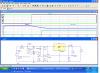
The schematic shows the power supply I'm using. V+ is unregulated 10-14V and J2 is a rechargeable 9V battery. T1 is connected to an AVR microcontroller pin with a pull-up. When the pin goes high I know I've lost external power and I'm running on the battery and an audible alarm sounds.

There are two problems I'd like to solve. First, I can get the audible alarm if another large load like a pump motor starts on the 12V external power source. Would a large filtering capacitor between V+ and GND solve the problem? If so, how do you determine the size? Right now the AVR pin connected to T1 tells me when I've lost external power. I'd rather have the AVR know when I'm running on the internal battery, which will happen if the external voltage source drops below the battery's voltage. Any ideas how to modify this power supply?
 

Attachments

  • Power Supply 12.gif
    Power Supply 12.gif
    17.6 KB · Views: 150
A couple of questions that will help decide the easiest/best way to do it:
What is the current load on the +5 volts and is it constant? If it is pretty constant we could sense the current from the battery with a simple circuit. Also this might allow us to put the filter cap on the other side (right) of the 1N4002 diode and make it smaller. Otherwise just a big cap on the 12 volts would help. Also make sure the 12 volts for your circuit comes from the source not from somewhere in the string of "stuff" (pumps and such).
 
Glad to hear that a capacitor will help. I can't always control the 12 volt source. In my case, I connect to a 12V light circuit on a boat's house battery bank. Occassionaly I get the audible alarm when the boat's fresh water pump starts, which I know is a large load. The load on the +5 volts is small but it will vary from 75 to 200mA. Any suggestions for the capacitor size and location and the circuit for sensing current from the battery will be appreciated. Note that the battery is trickle charged (6 - 10mA) when connected to external power.
 
Can't you just use J3-4 to control the alarm? Whenever the external power is present (>~5V) J3-4 is pulled low. A pull-up on J3-4 will give a high logic level when the battery is providing power.
 
Can't you just use J3-4 to control the alarm? Whenever the external power is present (>~5V) J3-4 is pulled low. A pull-up on J3-4 will give a high logic level when the battery is providing power.

That's exactly how it works right now. However, I do get the occasional alarm with a brief sudden voltage drop on the external power supply, which I hope can be solved with a large capacitor. Also, if the external power supply's voltage drops below that of the internal battery, I don't get the alarm because J3-4 is still pulled low even though I am running on the battery. With a 12 volt external supply that should not happen often but it is possible. That's why I thought it would be better to alarm only when running on the internal battery.
 
So what you need is a voltage comparator with a sluggish response, which triggers the alarm whenever V+ < Vbat for some minimum time. As a comparator has a high input impedance the capacitor value needed to slug the response will be modest.
 
How about this?
Power Supply 12mod.gif

The time constant for T1 base voltage change is ~ 100 secs but can easily be changed to suit the V+ voltage dip characteristic.
 
Alec,

I've never used one but I'll start reading up on voltage comparators. Thanks for your help.
 
Our posts seem to have overlapped in time. I draw your attention to post #7 and the one-transistor comparator I used to replace your T1.
Edit: this might require some modification to the AVR input circuitry. To avoid that, a second transistor could be added (I can redraw the circuit if needed).
 
Last edited:
Alec,

I am a hardware novice so I will need some explanation for your one-transistor comparator. I can see that the external power continues to provide current to the base of T1. Does the RC time constant (470000 * 0.00022) mean that T1's base will continue to receive current from the capacitor for about 100 seconds after external power is lost or some fraction of that time? With your circuit, what logic levels would I see at J3-4 when 1) no external power and capacitor discharged, 2) external voltage > battery voltage, and 3) external voltage < battery voltage. Thanks.
 
Vbat = 9V, so T1 (now a pnp transistor) base current can flow only when the base is less than ~8.4V. When the external voltage is >8.4 the transistor is turned off (no base current), so the collector voltage is pulled down by the 47k resistor towards 0V (it will only reach 0V if the AVR input pull-up is infinite resistance, which is why I said the AVR circuitry might need to be altered).
Assuming the external voltage is normally 12V, if it suddenly drops then the cap will discharge through the 470k resistor. The time to drop from 12V to 8.4V (a fraction of the 100 secs; it depends on V+ but lets say 30 secs) is the delay you get before the alarm trips. At 8.4V base current begins to flow and collector current raises the collector voltage (J3-4) to ~9V.
So the answers to your questions are
1) logic 1 (actually ~9V, so a tap half-way down the 47k resistor would be needed if the AVR runs at 5V)
2) logic 0, provided the AVR pull-up is > ~ 100k,
3) logic 1, provided V+ < 8.4 and delay expired, otherwise logic 0 if AVR pull-up > ~ 100k
 
Last edited:
Alarm

Here is a little different approach that will help eliminate the dead spot where the 12 volts is at say 8 volts. Don't know if that ever happens or not.
Gives about .1 sec for the big motors to start. The 10,000 uf cap is a couple of bucks.
 

Attachments

  • alarm1.PNG
    alarm1.PNG
    73.3 KB · Views: 124
This is the 2-transistor variant:-

Power Supply 12mod2.gif

T1 base is at ~9V, so if V+ (T1 emitter) > ~9.7V T1 is on, the cap charges, T2 is on and the AVR input (unmodified) is pulled down to ~0V.
When V+ drops below 9.7V T1 turns off, the 1N4148 prevents discharge of the cap via the external supply, the cap discharges through the 100k resistor and T2 base with a ~20 sec time constant. Only when the cap voltage has dropped below ~1V will T2 turn off. The turn-off delay is ~ 20 secs (easily changed). The answers to the questions are then
1) logic1,
2) logic 0, if V+ > ~9.7 (which it will be when the battery is being charged)
3) logic 1 after expiry of the delay.
 
Last edited:
Thanks guys! You've given me a lot to digest. I really appreciate the schematics and explanations. I don't want to change the existing 40 x 70mm board size so the 10,000 uF cap would be a problem. The 2-transistor option looks like a good solution. To date, I have only used npn transistors in my projects so I'll read up on the pnp type, get a few and breadboard the power supply to test. Thanks again!
 
One more possibility to consider, does the AVR microcontroller have analogue inputs?

If so, use one of them to measure 12v supply, and in the software of the micro decide when the 12v has failed for sufficient time before setting the alarm.

JimB
 
Update: I've just run a simulation of the 2-transistor variant. With a cap value of only 10uF the time delay is 3.5 secs.
 
:eek: JimB, You got it. He is using a micro. If you don't have an A to D just sample the current circuit again after a few hundred microseconds.
 
The AVR does have analog inputs. Wouldn't that require making assumptions in the software about the charged state of the internal battery to know when the external supply has dipped below the battery's voltage for some time? Alec's 2-transistor variant appears simpler. I've done some reading up on pnp transistors so I now understand the circuit. Can anyone explain (or point me to a good source) how to select the resistor and capacitor to determine how long it will take to discharge the capacitor? Is the time to discharge in seconds simply equal to the resistor size in ohms times the capacitor size in farads?
 
I don't think you need the 1N4148 diode in alec's circuit, so here is how it works:
When T1 is on (12 volts on) the cap will charge to about 11.7 volts.
When the 12 volts is within about .7 volts of the backup battery T1 will turn off and the cap will discharge thru the 100k and the base emitter junction of T2 until T2 turns off. As it is the turn off will be a little "messy" as the base emitter voltage reaches .7 volts, so I would add another 100K from the base of T2 to ground to finish discharging the cap.
The time constant in seconds it RXC (in farads) so for the voltage to get to .7 volts will take a little less than 3 time constants. (See link)

https://www.tpub.com/neets/book2/3d.htm
 
The 1N4148 diode is there only to prevent possible reverse-voltage breakdown of the T1 transistor, which might otherwise discharge the cap more rapidly than expected. Leave it out by all means.
I agree with Ronv's suggestion to add an extra resistor from base to ground to improve on the 'messy' turn-off. That should make the delay ~ 3*R*C as Ronv says (in the simulation without the extra resistor I was getting ~ 3.5-5 *R*C, depending on the type of transistor used for T2 and the assumed pull-up resistance at J3-4).
 
Last edited:
Status
Not open for further replies.

Latest threads

New Articles From Microcontroller Tips

Back
Top