Continue to Site

Welcome to our site!

Electro Tech is an online community (with over 170,000 members) who enjoy talking about and building electronic circuits, projects and gadgets. To participate you need to register. Registration is free. Click here to register now.

  • Welcome to our site! Electro Tech is an online community (with over 170,000 members) who enjoy talking about and building electronic circuits, projects and gadgets. To participate you need to register. Registration is free. Click here to register now.

DC motor

Status
Not open for further replies.

Geno03245

New Member
New to electronics. Four questions.

Building a 12dc motor timer

1. To figure the timer, specific information about the motor is required, right?

2. Specifically what info is needed about the motor.

3. What techniques are used to gather the info?

4. -or- is specific motor information unnecessary if a transistor or relay is used to turn on the motor?
 
What does a motor timer do? Is it just an on/off egg timer for the motor?
 
Last edited:
New to electronics. Four questions.

Building a 12dc motor timer

1. To figure the timer, specific information about the motor is required, right?
Yes.

2. Specifically what info is needed about the motor.

Motor type? (DC types: Permanent magnet, brush, stepping, series wound, shunt wound) AC types: shaded pole, induction, capacitor, universal)
Voltage?
Starting current?
Running current?

3. What techniques are used to gather the info?
Get a "data sheet" from the manufacturer

4. -or- is specific motor information unnecessary if a transistor or relay is used to turn on the motor?
No, the voltage/current rating of the switching device is determined primarily by the motor.
 
dknguyen

the 12V dc gear motor will be used to rotate a dial one direction for 25-35 seconds > then stop > reset for reverse >>>

when activated again, the motor will rotate the dial back to original position

the dial is part of the gas control for a residential water heater > the dial is moved from 'vacation' setting to the selected thermostatic setting. The function of the gear motor will allow people to turn down their energy consumption during hours when hot water is not needed
 
MikeMl

Thanks. Will research data sheet RF370CN-09950. KA032515 China.

Gear motor is from a 93 Ford truck designed to open and close heat-air duct baffle
 
That doesn't sound like a motor that you will find much info about. You should be looking for one that you can buy. ;) Most of the OEM automotive stuff is built to the auto makers spec an is not used anywhere else.

I just looked at the gas valve on my water heater. What does the temperature setting dial do inside the gas valve? It the temp setting dial just setting an electrical potentiometer, or is it doing something mechanical?

Do you have any evidence that "turning down" the temperature setting for say eight hours while asleep and then turning it back up the next morning actually saves any gas? It seems to me that the amount of gas required to keep the tank hot overnight just about equals the amount of gas to reheat it after it cools during the night. To win at this game, it seems it would have to be off for days or weeks (i.e. a true "vacation") :confused:

btw: now that I looked at the gas valve, I'm convinced that you will in fact need a limit switch. Otherwise, if you use only time to move the dial CW and then later CCW, even if the two times are equal, the running friction of a reversible motor will not be equal running both directions, so you will always be accumulating positional error. You need a definite limit at least in one direction to re-index the position each cycle.
 
Last edited:
MikeMl

You're right > there is no info on that motor. However today's testing showed that I can activate motor using VR15M121C relay powered by old radio shack 3G72 E149469 9V dc 350mA transformer. So motor question is tentatively solved.

By regulation, there is no electricity inside a residential gas water heater valve. If there was a controllable electrical component, the issue of making a timer would be simplified.

Ordinary tank water heaters don't have a switch option, yet they account for 13-16% of household energy bill. By contrast, residential gas furnace is turned on-off via electrically controlled gas valve, but no similar control exists for residential gas water heater. Redesigning residential water heater and getting FTC approval followed by Texas Railroad Commission approval would solve problem, but would require replacement of existing heater.

Can you save money by turning the water heater to 'vacation' except times when you need hot water? The answer is yes >> 'IF' you are willing to schedule hot water use 'AND' cut back hot water consumption the savings can reach 6-8% of total household energy bill.

Family chart for setting Water Heater Timer

Right now consumers have no automated control over their water heater. Some people may want a control. I have a control for my electric water heater > for the purpose of demonstration, I'm designing a cheap, DIY, off-the-shelf retrofit control for gas water heaters.
 
DAER
am dont know what you want now
if you want to control with the valve thats a circuit will do its but it need some chenge if you want we can do it
sorry to intervene in
 

Attachments

  • motor drive.GIF
    motor drive.GIF
    7.3 KB · Views: 1,444
Last edited:
the eagle

my electronic need is simple, but I have no experience in electronics

I have a reversible 12V dc gear motor >> when activated, I want the motor to rotate one direction for 8-10 seconds > stop > reset itself for reverse > next time motor is activated, it runs 8-10 seconds in reverse > stop > reset for reverse

I see that the 555 monostable timer circuit interfaced with a 4013 flip-flop is the answer. At this moment, I have no idea how to construct a working board.
 
ok,
mr.Geno03245
r u ready to bild it with your hand .this thing is not hardly if you like to do it
i,ll help you step by step
if you ridy tell me please .
if u have a diagram put it to go .
 
Last edited:
the eagle

Thanks

**broken link removed**

Need assistance

After one week of electronics > image shows where my knowledge stops:

Project overview: I have reversible 12V dc gear motor >> when activated, I want the motor to rotate one direction for 8-10 seconds > stop > reset itself for reverse > next time motor is activated, it runs 8-10 seconds in reverse > stop > reset for reverse

I see that the 555 monostable timer circuit interfaced with a 4013 flip-flop is the answer.

Unknowns
>Is layout good so far?

>Value for R1?
>Value for R2?
>C > my idea is variable capacitor ?? which model number would u suggest?
>555 pin 3 > where does it connect?
>555 pin 4 > where does it connect? resistor needed?
>555 pin 5 > where does it connect?

>4013 flip flop > I understand general concept: state Q(overline) or state Q
>where would Q(overline) and Q connect back into circuit?
>4013 > all pins > where do they connect

input invited
Thanks
 
Geno03245
ther are the differnt idea .
chenge the data of the ( R1,2,3,4-C1,2,3,4 ) as you need and it can do 4 stage .
please do that chenge and tell me about the diagram .
thank for continuation :D.
 

Attachments

  • TIMER 558.JPG
    TIMER 558.JPG
    24.8 KB · Views: 611
Last edited:
Geno,

I repeat:

Now that I looked at the gas valve, I'm convinced that you will in fact need a limit switch. Otherwise, if you use only time to move the dial CW and then later CCW, even if the two times are equal, the running friction of a reversible motor will not be equal running both directions, so you will always be accumulating positional error. You need a definite limit at least in one direction to re-index the position each cycle.

I have designed and simulated two different ways of doing it, but am out of time tonight to add details. You can look at this, but consider it unfinished...


Added Monday:

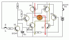
The circuit below is one way of driving a reversible DC gear motor. I'm assuming you want to push a button, the motor should run for a fixed time and then stop. When the button is pushed again, the motor runs for the same duration but in the opposite direction by causing the motor current to flow the other direction through the motor. Based on your motor specs I made the supply voltage 9V.

Since the button push must be "clean", I elected to use a momentary spring return type switch with three terminals, NC normally closed, NO normally open and C common. The Common is shown wired to 9V, and the NO and NC are wired to the SET and CLR inputs of a D Flip Flop. This "debounces" a flaky switch, to produce a clean clock signal for the second DFlop, which keeps track of the direction. Obviously, the circuit must be powered continuously for the DFlop to retain the information. The beauty of CMOS logic is that it draws very little power just sitting there powered. The funky Voltage sources V2 and V3 that control the switches are just the way this simulator models switches. The voltage source is just a convenient way of specifying when the switch is open and closed. Since I am modeling both the NO and NC sides of the switch it takes two of everything.

The second DFF is wired as a toggle, meaning it changes to the opposite of its current state every rising edge of the DB signal. The two outputs CW and CCW are capacitively coupled to the two 555 timers. It is the low going edge of the CW and CCW signals that trigger the 555 times alternatively. The 555s are wired as timers, meaning that when triggered, their output goes high for a time determined by the time constants R2C2 and R4C5, respectively. Since the other 555 is not triggered, its output is low, so current flows from the triggered 555, through the motor and into the 555 whose output is low, a poor man's H-Bridge

555s are rated to source and sink 200mA, so they should run your lightly loaded motor. If not, I have another circuit which will.

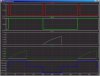
The plots from the simulation are attached. The top trace (Red) is the debounced button push, high when pushed, low when released. The second (green) trace is the direction flip-flop, showing how it changes direction every time the button is pushed. The next two traces (Gray and Dk Green) are from the RC timing networks in the two 555 timers, showing how they are triggered alternatively. The last trace is the current through the motor showing the three states: zero current when stopped, + current when running one way, - current when running the other.

To a first approximation, it does what you asked for, with one exception. I gave you the ability to adjust the CW running time independently from the CCW running time, because each 555 is independent of the other.
This is both a bad thing, and a good thing; bad because you will have to tweak the two periods, good because this way you stand a change of setting it up so that it travels the same distance both ways. If there was only one fixed period, I guarantee that you will accumulate positional error after each cycle.

As I was designing this, it occurred to me that you really shouldn't be using a push button but a toggle switch. The toggle switch intrinsically shows the position that the thermostat dial is set to. If you want to "turn it up", you can tell at a glance if it is "already Up", or if you need to move it to the other position. With a push button, there is nothing to tell you what position you are presently in (unless you add an indicator like a LED) which is driven off the Direction FlipFlop. Besides, the toggle switch greatly simplifies the circuit because you can eliminate both the debounce flop and the direction flop.

Now if I can convince you that you need limit switches to reindex it every cycle, you can eliminate the 555s, too.
 

Attachments

  • WaterHeater.jpg
    WaterHeater.jpg
    113.6 KB · Views: 498
  • WaterHeaterPlot.jpg
    WaterHeaterPlot.jpg
    214.8 KB · Views: 241
Last edited:
right mr.MikeMl
please loock at the diagram that i send it .
it,s the first and there are second to control with the way and time .
now i wating mr. Geno03245 to get his opinion about .
 
I am encouraged that I know nothing yet 2 people are helping my project. Thank you.

the eagle > I haven't learned the symbols you used in your diagram > give me 2 days study so my questions make sense.

MikeMl > yes, after testing motor I can see variability > Ford air blend door actuators have mechanical stop points > actuators come in many models > this type of gear motor runs slow, runs on DC, and is not so strong that it will break a gas valve. It is cheap and it is off-the-shelf. Tomorrow I am searching salvage yard for other types.

Vacation setting is wide band on the gas w-h control dial > thermostatic setting is also not precise > however over time, variation between factors may throw off timer > in a larger picture, I doubt that gas w-h controls were engineered to undergo continual on-off being proposed >>> hence my goal is to show that it can be done, not to give a definitive answer.

I am also working parallel design using Honeywell M847D1012 Replacement Damper Actuator Motor > this type motor opens heat-AC damper in office buildings (each room in office building has thermostat which controls damper motor located in duct above room) > motor works against a spring so once motor is turned off, the spring returns damper to original position. This option has favorable features > simplicity included where the motor is controlled via intermatic wall timer from Lowes + 24V ac transformer (no circuit board needed). Down-side is that motor remains 'on' to work against spring which costs against efficiency.

I want to show at least two options for controlling a gas w-h valve using simple off-the-shelf parts > having a control made with off-the-shelf-products makes the idea 'real' to everyday people > it will give a start-point to the conversation about w-h efficiency. Whereas no conversation exists today except people saying that no saving can be had > which assumes everybody will continue using energy the same as the past.

I see your schematic > of course it is way over my head > again, give me a few days study to find questions that make sense.
 
DAER
am dont know what you want now
if you want to control with the valve thats a circuit will do its but it need some chenge if you want we can do it
sorry to intervene in

Included image:
motor-drive-gif.30600


You need two resistors. One between Q4_colector and Q7_base and the other between Q9_colector and Q8_base.

Otherwise Q4 and Q9 will short'n burn.
 
Last edited:
Geno, go look at the post with the proposed circuit again. I added a description and some other thoughts.
 
Status
Not open for further replies.

Latest threads

New Articles From Microcontroller Tips

Back
Top