#include <pic.h>
#include <htc.h>
__CONFIG (0x3FFB);
//__CONFIG (0x120A);
#define _XTAL_FREQ 20000000
#define REEL_IN 0b00000001;
#define REEL_OUT 0b00000010;
int count = 0;
void delay_s(int k){
for (int i = 0;i<=k*100 ;i++){
__delay_ms(10);
}
}
void interrupt isr(void){
count++;
INTF = 0;
}
void main(){
TRISA = 0;
TRISB = 1;
TRISC = 0;
TRISD = 0;
PORTA = 0;
PORTB = 0;
PORTC = 0;
PORTD = 0;
ADCON1 = 6;
ADCON0 = 7;
GIE = 1;
RBIE = 1;
INTE = 1;
INTEDG = 1;
while(1){
while(count<=2){
switch(count){
case 0:break;
case 1 ORTC = REEL_IN; break;
case 2ORTC = REEL_OUT;delay_s(2);count = 1;break;
}
}
}
}
Hello everyone.. i'm a newbie here...
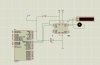
im doing a project where controlling a dc motor. My motor will turn infinitely until there has an interrupt and the motor will turn on the opposite direction about 2 second. i have done a simulation in proteus software and its work as i wish.... But during working in bread board, there are no output on the output port at PIC... can someone help me?? the program and circuit as above...
#include <htc.h>
__CONFIG (0x3FFB);
//__CONFIG (0x120A);
#define _XTAL_FREQ 20000000
#define REEL_IN 0b00000001;
#define REEL_OUT 0b00000010;
int count = 0;
void delay_s(int k){
for (int i = 0;i<=k*100 ;i++){
__delay_ms(10);
}
}
void interrupt isr(void){
count++;
INTF = 0;
}
void main(){
TRISA = 0;
TRISB = 1;
TRISC = 0;
TRISD = 0;
PORTA = 0;
PORTB = 0;
PORTC = 0;
PORTD = 0;
ADCON1 = 6;
ADCON0 = 7;
GIE = 1;
RBIE = 1;
INTE = 1;
INTEDG = 1;
while(1){
while(count<=2){
switch(count){
case 0:break;
case 1
ORTC = REEL_IN; break;case 2
ORTC = REEL_OUT;delay_s(2);count = 1;break;}
}
}
}
Hello everyone.. i'm a newbie here...
im doing a project where controlling a dc motor. My motor will turn infinitely until there has an interrupt and the motor will turn on the opposite direction about 2 second. i have done a simulation in proteus software and its work as i wish.... But during working in bread board, there are no output on the output port at PIC... can someone help me?? the program and circuit as above...