Continue to Site

Welcome to our site!

Electro Tech is an online community (with over 170,000 members) who enjoy talking about and building electronic circuits, projects and gadgets. To participate you need to register. Registration is free. Click here to register now.

  • Welcome to our site! Electro Tech is an online community (with over 170,000 members) who enjoy talking about and building electronic circuits, projects and gadgets. To participate you need to register. Registration is free. Click here to register now.

DC motor, consistent speed under different loads?

Status
Not open for further replies.
Yes I see what you mean now.

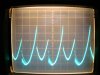
By my rough reckoning, @ 3 V = 5000 rpm
6 V = 10,000
9 V = 16,000
12 V = 19,000

Did by chance see of the RPM changed much with loading?
 
You're right.

I make it about 17000rpm@9V but it isn't easy to count the squares due to my shaky photography.

I make it 3.5 squares giving a period of 3.5ms, 60/0.0035 = 17,148rpm.

I'll see if I can count the pulses with my frequency counter, it might give be triple the frequency but I'll easily be able to figure that out.

Yes, the frequency does change with loading.

This is probably the simplest method of measuring the speed of a DC motor, it's fully compatible with PLL. It can also be made to be compatible with PWM, if a filter is added to get rid of the PWM, making what is essentially a buck converter.
 
Last edited:
Here's a better picture at 9V.

I've also noticed that the waveform changes when the motor is run in reverse which indicates that the motor isn't completely symmetrical. This normally happens because of the ways the brushes wear when the motor is normally only operated in one direction.

1) Better picture, 9V 1ms/div, 50mA/div
2) Waveform when connected in reverse, same 'scope settings as #1.

I've tried using a frequency counter but it didn't work. I measured a frequency of 30kHz which seemed to increase when I put a load on the motor. The counter is probably triggering at a harmonic and is changing when a load is applied (the waveform also changes shape when loaded). I tried adding a low pass RC filter 680R and 100nF but it didn't work. I also tried a 22µF capacitor in parallel with the motor and a common mode EMC choke to no avail.

The motor emits some pretty high frequency RF harmonics: I accidentally connected it to the 20MHz to 1.3GHz counter input and it read 300MHz which explains the TV and radio interferance generated by it. The harmonics probably extend well into the microwave band.
 
Hi,

Yes, the arc when the commutator switches is going to generate all kinds of stuff.
It might be hard to filter out because the filter has to have wide bandwidth too.
Maybe mount an antenna next to the motor to pick up the RF bursts, then count
them (chuckle) :)
Maybe high pass would help pick out the arc over points.

The back emf technique BTW has been used on various tape recording machines.
It's not perfect but it does work.
Hall effect sensors have also been used very effectively and there isnt much
of a problem with noise.
 
Maybe mount an antenna next to the motor to pick up the RF bursts, then count
them (chuckle) :)
Maybe high pass would help pick out the arc over points.

Good point. Looking at the waveforms, maybe get a good signal for freq counter by differentiating out that very fast edge I can see there on all the traces. Maybe try first putting the counter input probe near, but not touching, to try this out first.

I reckon differentiated pulse could be buffered up with a capacitively coupled 74HCsomething gate connected in linear mode (you know, with some neg feeback round it).

Of course with a brushless motor it's really easy to interface to one of the phases.
 
Last edited:
My previous post was supposed to have attachments.

Here they are:
1) Better picture, 9V 1ms/div, 50mA/div
2) Waveform when connected in reverse, same 'scope settings as #1.

With suitable filtering and Schmitt trigger such a system could easily be used with a PLL to form a very stable motor controller.

I've tried connecting an 8Ω speaker in series with a small DC motor before and it emitted sound proportional to the speed of the motor. Obviously the speaker will blow if it was connected for too long, with a load on the motor, to get round this an LM386 amplifier and speaker could be connected to the sense resistor. This could be used in a remote controlled car or robot for an engine sound.
 

Attachments

  • 9V 1ms better.JPG
    9V 1ms better.JPG
    1.6 MB · Views: 555
  • 9V 1ms reverse.JPG
    9V 1ms reverse.JPG
    1.6 MB · Views: 136
Hi,

Hey, that's better :)
 
Status
Not open for further replies.

Latest threads

New Articles From Microcontroller Tips

Back
Top