Continue to Site

Welcome to our site!

Electro Tech is an online community (with over 170,000 members) who enjoy talking about and building electronic circuits, projects and gadgets. To participate you need to register. Registration is free. Click here to register now.

  • Welcome to our site! Electro Tech is an online community (with over 170,000 members) who enjoy talking about and building electronic circuits, projects and gadgets. To participate you need to register. Registration is free. Click here to register now.

DC DC Converter Heating Issue

Status
Not open for further replies.

Suraj143

Active Member
Hi,

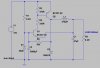
I made this discrete DC-DC converter. 12V to 5V converter, & I need 600mA of current.
The problem is Q2 transistor is getting extremely hot.After I changed it to BD140, But that also getting extremely hot within seconds. I changed couple of different value inductors as well, but Nothing helped.

How to solve this heating issue?
 

Attachments

  • DCDC.JPG
    DCDC.JPG
    41.8 KB · Views: 265
Why such a complicated switching regulator? What is it being used for?
For +12VDC to +5VDC, I would simply use a LM7805 voltage regulator. Those are rated at 1A, some as much as 1.5A. You would still need some form of heatsink for the 7805, as it would be dissipating 7V (12-5) x 0.6A = 4.2 Watts. Putting a 5 ohm (approx.) 5W resistor in series between 12V and the regulator would help dissipate some heat via the resistor, and require less heatsink for the regulator. At 600mA, the resistor would drop the voltage 3V to the regulator, making it regulate from 9V to 5V. The resistor would dissipate 1.8W at a 600mA load.
 
How to solve this heating issue?
Use a SMPS (switch mode power supply). Any linear regulator (such as your circuit) will necessarily dissipate 4.2W and get hot when dropping 7V at 600mA.
 
I made a discrete boost converter once on similar lines. It made a huge difference to performance (and therefore efficiency) using switching transistors instead of general purpose ones. Though to be honest your circuit looks as if it will change frequency and duty cycle if the output cap is changed or the load is changed, which is never good.
Better to use a chip like MC34063 (which has the advantage of being extremely cheap and very easy to use), much more efficient than a linear regulator and takes up much less space than a discrete design. Depending on your use-case you might want to set it of over 5v and put an LDO on the output.
 
I havent looked right into this so I might be wrong, however:
The Bc327-40 appears to be a high gain variant, 250, the Bd140 has a low gain around 25.
So I'd say the '327 in the original design is saturating properly while switching, whereas the '140 is probably not saturating and operating in its linear region hence the heat.
Capacitance might also be an issue being a larger tranny, this'll slow down switching speed, increasing dissipation.
R2 will need adjusting at the very least, and you might need to replace Q1 as well.
 
I made a discrete boost converter once on similar lines. It made a huge difference to performance (and therefore efficiency) using switching transistors instead of general purpose ones. Though to be honest your circuit looks as if it will change frequency and duty cycle if the output cap is changed or the load is changed, which is never good.
Better to use a chip like MC34063 (which has the advantage of being extremely cheap and very easy to use), much more efficient than a linear regulator and takes up much less space than a discrete design. Depending on your use-case you might want to set it of over 5v and put an LDO on the output.
Very nice idea.I made that as well.It worked nicely but the MC34063 IC gets hotter.I did not use external pass transistor.Just loaded 800mA from the chip.
 
I havent looked right into this so I might be wrong, however:
The Bc327-40 appears to be a high gain variant, 250, the Bd140 has a low gain around 25.
So I'd say the '327 in the original design is saturating properly while switching, whereas the '140 is probably not saturating and operating in its linear region hence the heat.
Capacitance might also be an issue being a larger tranny, this'll slow down switching speed, increasing dissipation.
R2 will need adjusting at the very least, and you might need to replace Q1 as well.

Very good info too.I made Roman blacks design.He uses the same.But I changed his feedback capacitor to a resistor & REduced the R2 to 330R.
Here what he has done.
https://www.romanblack.com/smps/smps.htm

I don't know how he has got 800mA test results from the same circuit with BC327.

What value transistor is good for this?
 
I thought I recognized the design.
I couldnt tell you the resistor, you'll have to do that yourself.
I think the Bc327 is rated for 800ma, its a lot for a To92 tranny.
 
I got the boost design from RB as well, tweaked it a bit too. Educational but I wouldn't do it again.
 
I think changing the feedback capacitor to a resistor messed up the circuit.
 

Attachments

  • SMPS buck converter.png
    SMPS buck converter.png
    167.1 KB · Views: 207
Re post #4. Of course you want it to change the duty cycle. I am an idiot, ignore me!
 
Hi,

In Roman Blacks circuit he used a feedback capacitor and a high value of R2.With that parts I cannot even a put a small load like 150mA, because the output voltage drops down significantly.

That's why I change it to a feedback resistor and a low value R2.

Now output is steady, but the Q2 is really hot.

What did you expect?, it's not a working circuit any more, why would you expect random component changes to continue working properly?.

As far as the original circuit goes, I've always thought it's a bit 'iffy', as it is relatively simple for what it does - so any changes are likely to seriously disrupt it's operation.

Why mess about?, just buy a cheap ready made module from China.
 
Every part in this design is critical for current limiting, relaxation frequency and startup-efficiency . The feedback cap could be improved with a series resistance to raise f and shorten Q2 surge pulse.

This includes Q2: hFE and GBW which are tradeoffs, L/R=T1 , C1*ESR=T2 , R5C1=T3 and C1/C2 ratio There are advantages to reducing LC product to raise frequency while maintaining rt(L/C) ratio for ripple impedance.

I tried a very precise simulation of all passive parts with sliders for ESR,C2,L,DCR,Rb,Rf,Cf and this was my conclusion. There will always be a tradeoff between overheating Q on startup or load regulation stability or excessive peak current. The feedback cap drops the zener voltage and there are critical time constants that make everything interdependent. Especially when high hFE drops to 10% on saturation.

Generally, these "special minimal" designs cannot optimize every tradeoff. and you will always find a bandaid with higher ESR or much lower L and be wanting current limiting features added and soft start.

Conclusion, get a more stable complex design like an OKI 3 terminal Buck regulator.
 
Here's a link to my Simulation if anyone wants to play around with it. You must drag the "Scope frame edge " up then recentre the schematic (edit) to see better https://tinyurl.com/y59vu6lb Then move sliders interactively, change anything your want. Q hFE is fixed when you choose it (properties) and not variable to 10% hFE when Vce=Vce(sat)
 
I've just thrown togther an oppsite circuit, 5v to 12v, the 12v is 600ma.
Not having time to wait for a Lm2577, I went with a lowly 7555, a logic level fet and a 2n2222 / zener for regulation.
It works very well for a bodge up.
 
Status
Not open for further replies.

Latest threads

New Articles From Microcontroller Tips

Back
Top