Guys & Gals,
I have a project to use a windshield wiper motor to drive a mini mill power feed. I converted a computer power supply for the juice and purchased speed direction control unit on eBay. I tested the electronics using a auto electric window motor and all worked as it should. I didn't have connections for the wiper motor at the time, but I did verify that at worked good.
So, now I have the project together, but the motor does not work as expected. It runs at a constant speed, doesn't slow down when I turn the speed controller down. When I turn the speed controller to stop and then reverse, the motor does not turn at all. I connected up the power window motor again and it works as it should; changes speed and direction of rotation.
I'm thinking the wiper motor is good, but has electronics that make it behave differently. So, my question is can I do something relatively simple to the electronics to get this motor to respond as needed? If so, what do I need to do?
If it can't be done with some fairly simple changes, I'll have to get another motor. I'm not doing this immediately because I have a lot of time invested in the motor coupling and mounting bracket for this motor.
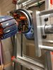
Below are a few pictures of the circuitry in the motor housing.
Thanks in advance for any input.
Roger Barker


I have a project to use a windshield wiper motor to drive a mini mill power feed. I converted a computer power supply for the juice and purchased speed direction control unit on eBay. I tested the electronics using a auto electric window motor and all worked as it should. I didn't have connections for the wiper motor at the time, but I did verify that at worked good.
So, now I have the project together, but the motor does not work as expected. It runs at a constant speed, doesn't slow down when I turn the speed controller down. When I turn the speed controller to stop and then reverse, the motor does not turn at all. I connected up the power window motor again and it works as it should; changes speed and direction of rotation.
I'm thinking the wiper motor is good, but has electronics that make it behave differently. So, my question is can I do something relatively simple to the electronics to get this motor to respond as needed? If so, what do I need to do?
If it can't be done with some fairly simple changes, I'll have to get another motor. I'm not doing this immediately because I have a lot of time invested in the motor coupling and mounting bracket for this motor.
Below are a few pictures of the circuitry in the motor housing.
Thanks in advance for any input.
Roger Barker
Attachments
Last edited:

 .
.