Thank you, KeepItSimpleStupid, Rumpfy and MrAl for these helps.
KeepItSimpleStupid:
OK, the real deal is you want to look at delta V/ Delta I. e.g. Suppose you built a 1 mA current source and with nearly the same components or say a voltage change, you could make that source output 1.1 mA.
So, you will look at the 0.1 mA and the difference in voltage. You could achieve, say 1e12 ohms of output Z, but it's not infinate.
I believe this is the ac resistance of the current source.
In this case Rac = 10^12 ohms that is not infinite.
Rumpfy: Thanks for this but I think it is not really my question. Sorry I can't explain it clearly.
MrAl:
In your first circuit, if you connect calculate the 'total resistance' 1v/1ma you get 1k.
So the current source sort of looks like a 1k resistor.
But wait, we can say the same thing about the voltage source because that also has 1v and 1ma.
So which is it that is the resistor, and which is the source?
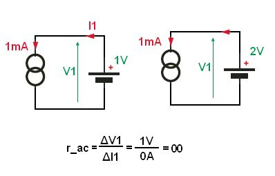
Also, if we connect a 2k resistor in series with the two sources, we still have 1v and 1ma for the battery.
But now the current source has -1v and 1ma, and the 2k resistor has 2v and 1ma, so that's 2v across the resistor and -1v across the current source, so now the current source looks like a -1k resistor. So how did the current source go from being a 1k resistor to a -1k resistor?
That is interesting. It is not really my question, though but I like to know that.
More exactly, if we connect the voltage source and current source to a circuit containing a few resistors and measure the voltage at some node N and measure 2.3 volts, then if we open circuit the current source and measure that same node and see 1.8 volts and then short the voltage source and reconnect the current source we see that same node measure 0.5 volts, and 1.8+0.5=2.3 volts, the same voltage we get with both sources active.
What this means is that the current source acts like an open circuit impedance that has the ability to force a current through the external circuit.
So we really have two completely different animals here, a source is not the same as a resistor, and so they are not handled the same way mathematically either.
To sum up:
1. The voltage source acts like a zero impedance.
2. The current source acts like an infinite impedance.
I am wondering if this is the way we use to prove that voltage source has internal resistance zero and current source has internal resistance infinity.
I often see that current source has infinite internal resistance. Then I tried to prove it but it is really confusing.
One of the answer that I received:
However, I then I feel more confused because there is another kind of resistance here, ac resistance.
I always why we don't calculate resistance of a current source by Ohm's law:
If we use this formula, the resistance of an ideal current source is not infinite but its value is a number.
What is the difference between resistances that are defined by two formulas above?
If I apply the two formulas above for an ideal resistance, the resistances computed from two formulas are the same. But when apply for an ideal current source, resistances calculated from each formulas are different. I really get stuck.
Why we don't apply the formula for an ideal current source and an ideal voltage source?
( I think the formula is not used because I always read that an ideal current source has infinite resistance and an ideal voltage source has zero resistance. Therefore, it is clear that the definition below is used in both cases.