Continue to Site

Welcome to our site!

Electro Tech is an online community (with over 170,000 members) who enjoy talking about and building electronic circuits, projects and gadgets. To participate you need to register. Registration is free. Click here to register now.

  • Welcome to our site! Electro Tech is an online community (with over 170,000 members) who enjoy talking about and building electronic circuits, projects and gadgets. To participate you need to register. Registration is free. Click here to register now.

Dashed circle in schematic???

Status
Not open for further replies.

pjones39

New Member
I am trying to build a circuit (schematic attached) and I have no idea how to wire up the part involving the dashed circle. What is this? Is it a part I need to buy? Is it a particular way of wiring? Thanks in advance.
 

Attachments

  • Piezoelectric Transducer Charge Amplifier.png
    Piezoelectric Transducer Charge Amplifier.png
    22.2 KB · Views: 1,229
That's a guard. It basically means that the op amp terminals are surrounded by a copper loop similarly as a shield would. Guards are typically driven at the same potential as the input. What it does is to reduce dramacically the leakage paths. If a high Z input is surrounded by the potential of the input, then there will not be leakage paths between the conductors.

With such high value resistors, you have to consider all leakage paths. Fingerprints are bad. You might also consider teflon standoffs for the components.

See figure #2 in the datasheet. https://www.electro-tech-online.com/custompdfs/2011/03/opa128.pdf
 
So I would pretty much just wrap the gaurd around the inputs 2 & 3 just like in figure 2? Where do the dots that are directly on top of the dotted circle connect to? input 2 wire?
 
You don't "Buy" a guard. It's a way of laying out the PC board. See the figure in the datasheet.

Laying out Electrometer amps is very difficult. Been there, done that.

Also, electrometer systems use triax cables. These are about $100 for 3'. The inner conductor is the signal. The inner shield is the guard and the outer shield is ground. Triax connectors come in two lung and 3 lug versions. The 2-lug version can easily be confused with BNC connectors.

Teflon standoff terminals can be purchased at US - Electronic Components Distributor | Newark.com
 
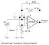
Dots on a schematic indicate a connection, in this case to ground.

The guard is primarily for PCB mounting of the components. It should be on both sides of all traces that go to pin 2 and 3, on all layers of the PCB. For a trace to pin 2 or 3, for example, it would consist of two additional traces connected to ground, one on each sides of the pin 2 or pin 3 trace.

All guards are connected to the ground connection on the PCB. Think of it as isolation around all the connections to pin 2 and 3. The idea is to drain away any leakage currents from any nearby traces that are at a different voltage from pins 2 and 3.
 
Wow, this keeps getting more and more confusing. Would the use of teflon standoff terminals eliminate the need for the gaurd?
 
A driven guard also helps to neutralize stray capacitance, particularly from the cables.
That's true for a voltage input, but not for a charge input, which this is, and which goes to the virtual ground input of the op amp. In this case you want all the guards connected to signal common.
 
Lift the op-amp inputs off the pcb and have your connections to them floating in the air.

Everything around there must be pristenely clean. Liquid freon was a good solvent for flushing the last little bits of contamination away.

That 10pf feedback cap must be of very high quality, like polysytrene.

For more info about charge amps and charge converters, look at the PCB Piezotronics website in their technical section
 
It could also indicate that a shielded transmission line must be used if the sensor elements are physically removed from the immediate input to the opamp.
 
Here is an example of a guard.
 

Attachments

  • GUARD.gif
    GUARD.gif
    37.8 KB · Views: 374
OK. So I am going to use teflon standoff connections and avoid the gaurd all together. I am also going to use a polystyrene or teflon 10pF and 100pF capacitor. I have found a 100 pF polystyrene cap, but I can not find anyone who manufactures a 10pF teflon or polystyrene cap... Who makes these???

Also, if I were to use a 100 pF cap instead of the 10 pF cap, what changes in performance would I see?
 
The 10 pf cap determines the gain of the amplifier. 100 pf will decrease you gain 10x. The xdcr produces a charge "Q". The op-amp's feedback will provide an equal and opposite charge through the feedback capacitor. Q = -CV, so -V = Q/C.
A good charge amplifier would not need the resistor in the feedback loop.
You determine gain and frequency response information by substituting a capacitor and a signal source for the xdcr. Gain will be Cf/Cin.
 
Status
Not open for further replies.

Latest threads

Back
Top