Continue to Site

Welcome to our site!

Electro Tech is an online community (with over 170,000 members) who enjoy talking about and building electronic circuits, projects and gadgets. To participate you need to register. Registration is free. Click here to register now.

  • Welcome to our site! Electro Tech is an online community (with over 170,000 members) who enjoy talking about and building electronic circuits, projects and gadgets. To participate you need to register. Registration is free. Click here to register now.

Daewoo Fridge (FR-4501W) circuit board fault

Status
Not open for further replies.

Matthew Hill

New Member
Hi all,

I'm an electrician by trade but am definitely a relative rookie when it comes to electronics.

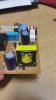
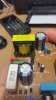
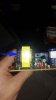
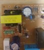
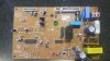
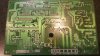
I'm having a go at repairing a faulty circuit board for my cousins Daewoo Fridge, now I have good reason to believe the transformer is the source of the problem. I have tested the transformer and has 120v at the primary side which is as expected, but then getting 70v on the secondary side (testing back to the incoming common for reference).

I was under the impression the secondary side supplying the rest of the board would be in the 20-12v range.

1- Would my assumption be correct?

2- Should I not be testing back to the incoming neutral for reference on the secondary? (on the two assumed terminals of the secondary side they both have 70v back to the incoming common and 0v between them.)

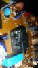
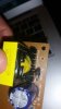
3- Is there any way to identify the transformer to hunt down a replacement?

I've attached a photo of said transformer. Am I right in thinking it's a SMPS transformer?

Thanks in advanced for any shared wisdom/help

Cheers,

Matt
 

Attachments

  • 20161102_120754.jpg
    20161102_120754.jpg
    672 KB · Views: 519
To check if the power supply is working, check betwean positive & Negative on the capacitor marked. It is a SMPS & the transformer is unlikely to be faulty, & is probably not available.
FRIDGE board.jpg
 
Thanks for the response. Just tested and teah 0 volts across the capacitor. both terminals of the capacitor have 70 v back to the common neutral.

Does this mean the transformer is faulty then? The SMPS transformer will give an output with or without a load present, correct?

I should have explained but the SMPS transformer has some physical damage to it, so I'm obviously suspicious that it's internal windings are shorted.
 
Hi Mathew,

We are getting a lot of new members from Australia/New Zealand recently. Which part are you from. If you put it next to location on your user page it will display in the box at the left of your posts. Knowing where members are from helps us with replies. In this case we know what your mains voltage is.

The power supply looks fairly standard.

In a switch mode power supply (SMPS), most often what looks like a transformer is actually an inductor (may have a primary and secondary windings), so the input output voltage relationship of a transformer does not apply.

Just one point: some SMPS will not work correctly without a minimum load current: 50mA to 100ma load would be a good start.

A common fault with boards that have large/heavy components, that use the soldered contacts for mounting, is joint or track fracture.

Also, the board appears to be made from a brittle material, rather than fibre glass, so hairline fractures of the traces (tracks) may occur, especially due to the vibration from the fridge compressor.

The solder can also get crystalline and go high resistance (this is not always obvious). To correct this, all joints need to re-flowed with additional solder/flux

Most SMPS have an opto coupler for isolation between the mains supply and low voltage supply. Opto couplers can go 'soft' and need to be replaced.

Another common failure with SMPS is deterioration of the electrolytic capacitors, especially the large reservoir capacitors on the mains and low voltage sides.

You say that the inductor (transformer) is damaged: in what way? Is it mechanical damage or overheating?

Can you post a picture of the whole PSU board?

spec
 
Last edited:
Hi Matt,
Measuring voltages with respect to mains neutral either on the primary side or secondary side is meaningless. A switch mode power supply basicaly workgs like this. The mains input comes in through a filter (Also with MOV transient supressors between live and neutral.) It is then rectified with a bridge rectifier and smoothed with a capacitor. It is then chopped into a high frequency (Tens to hundreds of KHz ) rectangular wave and this is fed to the transformer. It is then rectified and smoothed from the transformer secondary to give the DC output. The opto coupler that spec mentioned is used to isolate the feedback signal (Which controls the output voltage.) between the mains side and the output side of the transformer. The reason for all this is to reduce the size and weight of the transformer and also the cost. If you are taking voltage measuments on the primary side they would normally be referenced to the negative of the input smoothing capacitor. (Probably the 12 uF 450 V capacitor at the middle bottom of your picture.) If you are taking voltage measuments on the secondary (Output ) side the measurments would normaly be referenced to the -Ve output terminal. Most faults I have seen on switch mode power supplies have been on the primary side and have caused by failure of the switching transistor or control IC. This normaly causes a fuseable resistor or fuse to fail on the mains input. If you could post clear pictures of the whole board from both the component side and the track side we may be able to help you find the fault. Could you also mesure the DC voltage across the teminals of the 12 uF 450 v capacitor. (I would expect around 330 volts.)

Les.
 
Is this a crack in the board or some shadow at the tip of the arrow.

Measure the resistance of the two or three secondary and primary terminals of the transformer. They will be low.
Also the resistance of the big white ceramic resistor and the the two 120k resistors. Brown, red, yellow.
If the 120k's are open the SMPS won't start. If the design is what i think it is.

It is not wise to cross measure primary to secondary, for you or your test equipment.
When measuring on primary side use primary common and on the secondary use secondary common.
The transfo isolates mains from the secondary.
cheers

FRIDGE board.jpg
 
Hi all,

Apologies for the slow reply on my part, currently studying for exams I have over the next few weeks so the repair is taking low priority for the moment.

Really appreciate all the replies, wasn't expecting such great input! The full story with the board is that my cousin purchased this fridge second hand and before they ever got a chance to turn it on and actually test if it was working or not he removed the cover protecting the circuit board to try and fit the fridge below some shelving, it did not and the SMPS transformer took a physical knock against the cupboard.

Hence what I was trying to do was test to see if the SMPS transformer was still working or if the knock has damaged it.

Spec, I've attached some additional photos and updated my profile.

Les Jones, I'll test the D.C. voltage at the capacitor next time I've got a minute and let you know.

Pfofit, That is an incredible spot!!! I'm impressed.. Yes the board is damaged from the impact and exactly as Spec mentioned there were several of the tracks that had cracked and had no continuity. I performed a temporary and very dodgey solder job to bridge the cracked tracks with a crappy soldering iron I had available at my house. I've got access to very good equipment at my university so if I can find it's repairable I'll invest some time there and reflow the solder as mentioned and clean up/re-do my patch fix.

I guess at this point I'm looking for a way to test if the SMPS transformer is still working?

Many thanks everyone. :)

Matt
 

Attachments

  • 20161104_091018.jpg
    20161104_091018.jpg
    708.7 KB · Views: 400
  • 20161104_091211.jpg
    20161104_091211.jpg
    481.5 KB · Views: 475
Hi Matt,

That sounds hopeful.

Just a few words about the inductor (transformer).

An inductor can be damaged in three ways:

(1) Winding short
(2) Winding open circuit
(3) Mechanical damage

That type of inductor will have a brittle ferrite core which is easily cracked. But a cracked core is not fatal. If the core is cracked all you need do is to ensure that the crack is closed so that the magnetic circuit is maintained. This is normally done by special tape, or sometimes thin epoxy glue and tape to hold the two sides of the crack firmly together.

In general, other mechanical damage will not matter.

spec
 
Last edited:
Matthew.
You should use a wire bridge on those cracks, don't rely on the solder only. The crack makes the board prone to flexing.

Did a quicky reverse engineer in pencil for ya on the smps and output. Might / probably has errors.;)
Comes with a money back guarantee.
edit: added 1 ohm 3 watt resistor after bridge
Note. the difference in ground symbols I used for grounds on both sides of the transfo. Don't cross measure.

Can you get a couple angles pics from all sides on that tranfo. Focus is still off a tad.
Whats the part number on IC5 ?

IMG_1399.JPG
 
Last edited:
Hi, all done with exams! Happy days.

I've since been able to test the circuit board with the fridge and hence a load. The fridge came to life, but have found that the inductor(transformer) must be damaged badly. My assumption would be a damaged winding and resulting open circuit because the inductor was giving some arcing sounds and the outputs were turned off.

pfofit, thanks for the circuit diagram. At this stage of my understanding I can't take too much from it unfortunately haha, I understand (to a degree) the individual components but not what the arrangement results in.

I've attached some more photos for your interest and the part number on the IC5 is: 1L0380R.

As per previous posts those resistors all tested okay and the voltage across the 450V capacitor was 320v D.C.

Is it possible to find a replacement inductor(transformer)? Or will it not be repairable if the inductor(transformer) has a damaged/open circuit on one of the windings?
 

Attachments

  • 20161117_110744.jpg
    20161117_110744.jpg
    186.3 KB · Views: 341
  • 20161117_110757.jpg
    20161117_110757.jpg
    225.8 KB · Views: 392
If the transformer is faulty then you wont get a new one. The only other option is remove the 240v parts of the SMPS, & use a 2A switchmode plug pack & wire it across the capacitor. The voltage is most likely 12V dc, but just check the relays the clue there will be there operating voltage. Other option & more expensive is replace the board, the one in my Westing house fridge they wanted $200 for the board.
 
Hi again
I've since been able to test the circuit board with the fridge and hence a load. The fridge came to life, but have found that the inductor(transformer) must be damaged badly. My assumption would be a damaged winding and resulting open circuit because the inductor was giving some arcing sounds and the outputs were turned off.
Something isn't right. If the smps secondary has no output then the fridge should not come to life.
The relay #1 needs to come in to supply the compressor and that relay needs low voltage DC ~12 volts and that comes from the smps.
Unless the relay contacts are stuck. Measurement of the contacts should have open resistance.
4.jpg


There is a LED that sometimes is a smps power on, cpu sees power on or is used to flash out error codes.
Is that red led lit?

Also you need to measure the outputs of the SMPS and the 5 volt regulator.
I've marked up your pic as to where the measurements are to be taken from. I think. Report back those DC voltages. DId you set meter to DC when measuring secondary ?
2.jpg


The tranny images are still blurry for seeing details. The ferrite cores is made up of to "E's" glued together in the middle as indicated in my red lines.
One can see the joint in the blue circle, it is slightly off. No-never-mine unless it is broken/ unglued there. The core may also be broke down thru the center which will be hard to see. Check to see if you can move the E- cores and that they are still glued. Not a lot of force, just enough to see if they are still intact. The second pic may be the angle or just cheap manfacturing but the core looks to be skewed.
1.jpg


3.jpg


Are you sure the arcing is coming from the tranny?.
Is it a slow sharp snap snap snap or sound like bees buzzing?
Have a good look at where the wires coming out of the bottom of the tranny are wrapped and soldered to the pins that hold it on the board.
MAke sure the wires are not broken where they wrap around the pins.
Where did the tranny get whacked, side, top, left, right.? and how hard. It does not appear to be dented or nicked and there appears to be no discoloration from heating etc.

The diode in blue in the first tranny pic i posted above has a weird bend at the board. Normally do not see a lead bent that close to a component due to risk of damage. Did that get hit also . Have a close look at that diode for chips cracks etc on the bottom.
Where was the board mounted physically on the fridge.?
 
Last edited:
Hi pfofit,
On another thread relating to the control board in a freezer we came to the conclusion the NC contacts on the relay were used to control the compressor. Could that be the case with this fridge ? Could the OP check for continuity between the AC and Comp connections on the edge of the board with no power to the board. This is a Link to the freezer thread.

Les.
 
Debe that sounds like a good solution. I've attached a photo of the compressor relay, I've interpreted it as being 12v DC. Would I need to get one of a certain frequency? Or the DC output will be the only consideration. Also I have already contacted Westinghouse and yeah spot on for the price of a replacement, my cousin purchased the fridge second hand so not going to spend any great amount of money on parts, more pursuing this out of interest.

pfofit. The relay contacts are open and the LED light hasn't come on at any point.

I'm quite confident the arcing was coming from the transformer it was making a crackling sound like there was a bad connection. If you see the video I've uploaded at this link:

https://tinypic.com/player.php?v=2952ycp>&s=9#.WC7b-NxicyE (Video of testing resistance of the transformer windings 1 & 3)

I've demonstrated where I believe the arcing was coming from which is between the (1) & (3) of the primary side of the transformer. When I apply pressure to the top of the transformer it goes from infinite to negligible resistance. It's the most difficult one to get a good look at but It does look as though that pin has possibly come dislodged and therefore not connected to the associate wire properly. Would it be reasonable to remove the transformer from the circuit and try to re-solder the wire back to the pin?

The diode appears to have been bent that way intentionally and not from the knock. The board is mounted on top of the fridge towards the back.
 

Attachments

  • 20161118_203854.jpg
    20161118_203854.jpg
    386.1 KB · Views: 357
The transformer took the knock as shown in the picture attached.
 

Attachments

  • 20161118_212709.jpg
    20161118_212709.jpg
    305.2 KB · Views: 343
  • 20161118_213014 copy.jpg
    20161118_213014 copy.jpg
    219.5 KB · Views: 264
Hi Les.
Thanks for the link. Just read thru that link. Yes, that relay was using a normally closed contact. Just a thermistor circuit controlling the transistor.

This relay is a normally open. SPST. https://pdf1.alldatasheet.com/datasheet-pdf/view/226322/MACOM/OMIH-SS-112LM.html
The second smaller relay is for defrost mode probably around 5 amps. Can't have the compressor running while defrosting the evaporator.
Had Matt check the contact and it is open, so something must be getting to the relay to bring it in.

Hmmm
Matthew? When you say "coming to life" do you mean the compressor runs and things get cold , the display lights up or both?
Did you get around to the dc voltage measurements?

Much more better pics this time.
Forget about my ramblings about the diode, bent lead looks to be on purpose & normal in that pic.
However the tranny definitely got whacked.
It's time to pull the tranny and inspect the wires coming out from the wrapping and connection to the board pins.
After you pull it take a sharp pic of the underside of him before you do anything to it. A couple angles to get the pins and wires.
A pin may be broken/loose from the base but the wire connection is the important bit.

Does that core move around freely, hopefully it's just pushed aside and there was enough play and hasn't broke the center core that is not visible. Don't try and move it back.
Make sure that the D5, R4 and the c2 cap are good and solder connections are nice and connection foils are not cracked.
If'n the thing is toast, as mentioned you will need to get a 12 volt SMPS wall wort to replace the 12 volts.

Have you found a tech sheet for this guy. A sheet of paper folded up, hidden somewhere behind a kick plate and buried near the compressor or behind the user panel. A lot of times they grow legs and disappear. Among other things, the tech sheet would probably tell you what the LED is for.
We don't get a lot of daewoo stuff over here.
 
Hi pfofit and Matthew,
Lookin at the pictyre of the etch side of the board in post #8 the solder joint to pin 1 of the transformer doed not look very good. I am wondring it this pin on the transformer is a bit short and the solder is just a blob covering the hole. When pressure is applied to the top of the transformer it could be forcing the pin into contact with the solder blob. I suggest removing the solder from this pin to inspect it to prove or disprove this theory.

Les.
 
Hi Les.
Thanks for that reminder.

..... there were several of the tracks that had cracked and had no continuity. I performed a temporary and very dodgey solder job to bridge the cracked tracks with a crappy soldering iron I had available at my house. I've got access to very good equipment at my university so if I can find it's repairable I'll invest some time there and reflow the solder as mentioned and clean up/re-do my patch fix. Matt

In addition to what Les suggested.

Matthew? Have you got around to doing the clean up and bridging the broken traces with a wire?
I have an old wire wrap roll that I strip and use for this. I think it's like 30 gauge. Anything smallish, just don't use some big ugly #12.
Don't overheat the traces, they'll lift.
 
Status
Not open for further replies.

Latest threads

New Articles From Microcontroller Tips

Back
Top