Electro Tech is an online community (with over 170,000 members) who enjoy talking about and building electronic circuits, projects and gadgets. To participate you need to register. Registration is free. Click here to register now.
Welcome to our site! Electro Tech is an online community (with over 170,000 members) who enjoy talking about and building electronic circuits, projects and gadgets. To participate you need to register. Registration is free. Click here to register now.
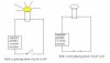
I mean when the circuit is broken, i have to make a bulb glow and it should stop glowing when circuit is closed... the bulb may be in parallel or series,
Please see this below Picture to get my question
battery positive terminal to a resistor. the resistor to the bulb. the bulb to the battery negative terminal. place a switch in parallel with the bulb.
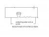
Here's how I do this. With the switch closed, the supply current is only 2uA. With the switch open, the current through the load is determined only by the load resistance and supply voltage, with no current wasted.
The FET can be almost anything that has a Vg < (supply voltage/2), a Vd> (supply voltage), and an On-resistance small compared to the load resistance.
battery positive terminal to a resistor. the resistor to the bulb. the bulb to the battery negative terminal. place a switch in parallel with the bulb.
yes...i'm using water as a switch, resistance of water is high,
i dont know what resistance i should use,
and my other question is that the switch will be on for a very long time like 24 hrs a day, will this decrease the battery life? Battery i'm using? if yes, i may require a alternative
Here's how I do this. With the switch closed, the supply current is only 2uA. With the switch open, the current through the load is determined only by the load resistance and supply voltage, with no current wasted.
The FET can be almost anything that has a Vg < (supply voltage/2), a Vd> (supply voltage), and an On-resistance small compared to the load resistance.
Since the 4.7meg resistor in my circuit can only source 2uA (from 9V), then if the resistance of the probes in the water is less than about 1meg, the FET will turn off because the gate voltage is less than Vt. If you know the effective resistance of your probes in water, you could select the gate pull-up resistor based on the ratio...
With 4.7meg and probes immersed, the battery current is only 2uA, which most batteries can source for a very long time...
This site uses cookies to help personalise content, tailor your experience and to keep you logged in if you register.
By continuing to use this site, you are consenting to our use of cookies.