Continue to Site

Welcome to our site!

Electro Tech is an online community (with over 170,000 members) who enjoy talking about and building electronic circuits, projects and gadgets. To participate you need to register. Registration is free. Click here to register now.

  • Welcome to our site! Electro Tech is an online community (with over 170,000 members) who enjoy talking about and building electronic circuits, projects and gadgets. To participate you need to register. Registration is free. Click here to register now.

Current limiter

Status
Not open for further replies.

Kane2oo2

New Member
got another question :p

if i cant understand something it really bugs me so i have to keep asking these questions lol :lol:

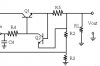
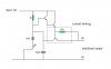
anyway .. how do these current limiting circuits like the one below work (R5 & Q2)
ive read that the voltage over R5 is not sufficient to switch on Q2 until a "larger" current is produced

but isnt Q2 switched on .. and just not able to conduct? as the +ve voltage is at the emitter side?

it would be helpful if someone could explain the circuit in simple terms (for a simple person)

Kane
 

Attachments

  • limiterC.JPG
    limiterC.JPG
    10.8 KB · Views: 442
I did not completely examine the circuit, but it appears that Q2 is not operating as a switch. Instead, a voltage difference across R5 changes the current through Q2. That current will "pull" base current from Q1, which lowers the emitter current of Q1 and effectively limits the circuit current.
 
oh ...i think i see now

i created this next circuit from the book i am using, it seems easier to follow.

so the resistor in this circuit drops the voltage going through it ...and so if the current is around 100ma then there will be a difference between the emitter and the base of around 0.68 ...enough to activate the transistor and pull the current from the uppermost transistor?

if this is the case...how can the current flow if the emitter is also connected to the +9v?
or is it the difference between the base of the top transistor and the emitter on the bottom transistor?

Kane
 

Attachments

  • limiter.JPG
    limiter.JPG
    12.1 KB · Views: 443
When the load increased to 100mA, the output is 9V - 0,68V so the emitter voltage about 8,32V the base remain 9V. The NPN transistor can open if the base voltage about +0,68V higher as emitter voltage, and this is independent what voltage sitting the emitter.
 
current limiting

Pertaining to the firs circuit that was posted. When the voltage drop across R5 equals approximately 0.7 volts, Q2 turns on and the voltage on
the collector is approximately 0.2volts more positive than the emitter voltage.
 
Status
Not open for further replies.

New Articles From Microcontroller Tips

Back
Top