Continue to Site

Welcome to our site!

Electro Tech is an online community (with over 170,000 members) who enjoy talking about and building electronic circuits, projects and gadgets. To participate you need to register. Registration is free. Click here to register now.

  • Welcome to our site! Electro Tech is an online community (with over 170,000 members) who enjoy talking about and building electronic circuits, projects and gadgets. To participate you need to register. Registration is free. Click here to register now.

current control

Status
Not open for further replies.

plumber

New Member
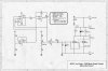
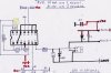
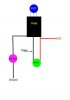
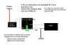
I found this site and saw specific solutions in diagram being exchanged. I am so close I can almost taste the diodes! Would some one please help me design the best circuit for my project...a diagram w/ part #s and some patience. I am a plumber in over my head and a week ago I didn't know spit. I simply need to control current without a huge drop in voltage. This is for an electrolysis project. The load simply being distilled water, anode and cathode and a current that will continually climb as the water takes on metallic particles and ions. Starting with a 30vdc source, I must keep the current between 2 and 8 mA's through out the process. SO, for this application, which would be better: 1. A sink, bipolar transistor, a resistor and 2 silicon diodes? 2. 2 NPN BJT'S and 4 resistors? 3. A voltage regulator (LM317), a N channel JFET and a resistor? 4. Or a fixed resistor in series with a variable resistor...which I would have to adjust constantly. Here is what is pertinent: I am trying to learn as fast as I can. However, I need the simple solution with the least amount of voltage drop. I guess "current limiting diodes" is a dying technology. I really need to get this done...my brain will have to catch up later. Part #'s, component values and descriptions is what I really need. If I cant specify values and ratings, I cant buy what I need. Even a example schematic of one of these circuits would help. So, I need mercy and help for now...but I do find this fascinating and plan on making it a hobby when I finish wrapping my brain around the theory,terminology and applications. Sorry for the long post.
plumber
 
You can't control the current and voltage independently. If you want to hold the current at somewhere between 2 and 8 mA, that's fine but the voltage needed could be anything.

As I understand it, 30 V will be enough. That isn't too difficult to handle, as even if your current limit circuit has to drop the entire voltage, you are only getting 0.008 * 30 = 0.24 W of heat in your transistor.

This is a good current limiting circuit.

**broken link removed**

Q1 is the one that takes the current and generates the heat. Rsense is the one that controls the current. The voltage across Rsense is 0.7 V (set by Q2) so it wants to be about 100 ohms to get 7 mA
 
Thank you Diver 300,
Q being a transistor right?
 
I think a PWM would be the simplest way for you to control the current,which is adjusted by a potentiometer,this will enable you to control the amps from zero to whatever the electrolysis cell peaks at.However,there is another very important factor to consider,to enable distilled water to conduct the current flow from anode to cathode,you need some form of catallist,this is usually done by adding a small amount of one of the following;Sodium Hydroxide(which is the cleanest)Bi-carb,Baking soda,vinegar or salt.also the distance between the two electrodes will make a big difference to current draw.Now for the big problem;The proccess will produce Hydrogen gas,which is extremely explosive(other gasses will also be produced which are poisoness)also the materials that the electrodes are made of are important,ferrus metals will produce sludge (oxydation) 1 soft & 1 hard electrode will result in the softest depositing it's self on the hard one.2 stainless steel electrodes remain stable.So my advice is to be very carefull,Remember what happened to RB11?(This airship went up in flames in seconds)
GOOD LUCK !
 
Current can be controled in many ways, depending of the ampage range and whatever you want to control. eg; very low amps can be controled by a potentiometer,high amps need a circuit that will cope without 'frying'
PWMs are considered to be the best and most reliable way to do this.
So, 1st, what do you want to control ? eg; voltage,ampage draw ect.,
I will suggest the easiest PWM circuit to build.
 
happy new year 1st of all.....and thanks for the help... for my project we are trying to find out if we can control a current without changing the value of the voltage of a circuit..... is that possible....?

sorry for the late reply....
 
tblo163.....i have the details of the project that i am suppose to do.....

3 components: voltage supply; the current control circuit and a potentiometer.

eg: we supply the circuit with a 12v supply, and by using the current control circuit, we control the current and at the same time we maintain the 12v of the circuit.....

is it possible.....?
and if so how.....?
 
maintaining voltage

tblo163.....i have the details of the project that i am suppose to do.....

3 components: voltage supply; the current control circuit and a potentiometer.

eg: we supply the circuit with a 12v supply, and by using the current control circuit, we control the current and at the same time we maintain the 12v of the circuit.....

is it possible.....?
and if so how.....?
As suggested, the current is to be controlled with a PWM,and provided the input voltage supply is stable ,the voltage will be maintained.eg; voltage supply from a transformer.is ok. whereas from a battery it will reduce 'go flat'
 
As suggested, the current is to be controlled with a PWM,and provided the input voltage supply is stable ,the voltage will be maintained.eg; voltage supply from a transformer.is ok. whereas from a battery it will reduce 'go flat'

we are supplying the circuit with input voltage from a power supply. will the voltage still be maintained.....?
how do you control a current using PWM....?
 
Pwm

we are supplying the circuit with input voltage from a power supply. will the voltage still be maintained.....?
how do you control a current using PWM....?

The normal basic PWM has a N channel mosfet,so the negative of the motor is connected to the 'drain' of the PWM,
the positive is common to both the motor and PWM+ ,the negative (ground) is connected to the 'source' of the PWM. Bear this in mind:- the case of the mosfet is physically connected to the 'drain' pin of the mosfet, so the heat sink should NEVER be grounded. The current is adjusted by the potentiometer that is installed on the PWM circuit board,or by remote if you extend the wiring from it.An analogue ammeter can be connected in series with the negative supply.If you intend to use a digital ammeter, a shunt must be used if the ampage exeeds the rating of the meter. I could create a diagram if you need one. Give some indication as to what device you are controlling,
voltage,max current draw ect; If you intend to run the appliance at the constant maximum ampage,you will need to make sure the PWM is suitably rated to cope.

duly noted. we are controlling the current. can you create a diagram to be used for referencing purposes.....thanks so much....
 
PWM Diagram

duly noted. we are controlling the current. can you create a diagram to be used for referencing purposes.....thanks so much....
Try these for now,any thing else, let me know. Terry.
 

Attachments

  • PWM.jpg
    PWM.jpg
    1.1 MB · Views: 238
  • PWM Scematic.jpg
    PWM Scematic.jpg
    2.8 MB · Views: 213
  • PWM schematic.JPG
    PWM schematic.JPG
    8.9 KB · Views: 229
PWM Diagram

This is the circuit I use to switch on the unit and protect it from over loading,I use a re-setable cicuit breaker,
rated so that if the maximum ampage of the PWM is exceeded it trips out.
 

Attachments

  • wiring.JPG
    wiring.JPG
    17.3 KB · Views: 184
tblo163, in post #14, in the second diagram..what are you using to represent the big block with numbers? is it an IC....?
 
tblo163, in post #14, in the second diagram..what are you using to represent the big block with numbers? is it an IC....?

It is an IC, it's a LM324N Quad op Amp 14 pin, this IC is the most commonly used for PWMs.
it has 4 transistor cicuits,so there is no need for any extra transistors,I,ve sent you the data sheet.
I allways use a 14 pin socket to mount the IC, this enables you to insert the jumpers for pins 2,12,8 &9,under the socket,and it saves soldering the IC directly. Terry.
 

Attachments

  • LM324N.pdf
    143.4 KB · Views: 155
Last edited:
PWM PDF Improved version

This is an improved version, with the schematic and components list Terry;
 

Attachments

  • PWM PDF.pdf
    2 MB · Views: 325
thanks for the help terry. sorry for the late reply. appreciate it.

another thing....the IC you recommended is out of stock in my country. could I use an alternative such as the TEXAS INSTRUMENTS LM224N
 
Last edited:
Status
Not open for further replies.

Latest threads

New Articles From Microcontroller Tips

Back
Top