Continue to Site

Welcome to our site!

Electro Tech is an online community (with over 170,000 members) who enjoy talking about and building electronic circuits, projects and gadgets. To participate you need to register. Registration is free. Click here to register now.

  • Welcome to our site! Electro Tech is an online community (with over 170,000 members) who enjoy talking about and building electronic circuits, projects and gadgets. To participate you need to register. Registration is free. Click here to register now.

Crystal Radio only gets a far away station?!

Status
Not open for further replies.
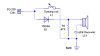
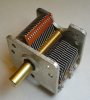
I need help with a crystal Radio first i used a ~70ft and ~20ft in the air, with that i only got static. But when i brought a connector to hook up to my dad's antenna, it got in WJLS which is ~80 miles away. Schematic is included(Crsch.png), plus picture of my dad antennas i tried it on.
**broken link removed**
 

Attachments

  • Crsch.png
    Crsch.png
    4.5 KB · Views: 423
Perhaps because there's no capacitor to act as a tank and it's only tuning with whatever stray capacitance is associated with the antenna or headphones? Most simple crystal receivers use at least two caps, one before the diode to act as a tank circuit with the inductor to provide for tuning, and one after the diode to smooth the output to the headphones. A simple Google search for crystal radio schematic will net you plenty of more sophisticated designs that use only a couple of extra dirt cheap components and provide significantly better results.
 
In order to receive other stations, you need to be able to tune to their precise frequencies. Without a capacitor with the inductor, you can't really tune it very precisely, and you will not get as wide a range.
 
Last edited:
In order to receive other stations, you need to be able to tune to their precise frequencies. Without a capacitor with the inductor, you can't really tune it very precisely, and you will not get as wide a range.

hi D8.
If its the same crystal set 'delph' was posting to the Chat room, the Coil has an adjustable slider take off contact along its length.
The idea is to tune it, you move the slider along the coil.

E.
 
Last edited:
eric, that type of tuning circuit is at the whims of even trivial capacitance, up to and including the antenna itself!

I've always read that the simplest possible AM receiver that was practically usable was an inductance and capacitance as a tuner, a diode as a detector and a second capacitors as a signal buffer and to prevent feedback from the headphones.

hi S,
I appreciate what a 'good' crystal requires, I built enough of them during the 1940's!:rolleyes:

But as always we are being asked about the crystal set kit the OP has built.
I saw an image of the built set on Chat, it had the tuning method I described.

E.
 
hi D8.
If its the same crystal set 'delph' was posting to the Chat room, the Coil has an adjustable slider take off contact along its length.
The idea is to tune it, you move the slider along the coil.

E.

Thanks for pointing that out, Eric. It still doesn't seem like a very effective way to tune it, though. It is probably even sensitive to the capacitance of your hand as you're moving the tap. I'm sure it is also sensitive to any electromagnetic interference other than radio waves, and that could be why you're getting mostly static.

DJ, can we see the photo you showed Eric in chat? It might help here.

Best wishes,
Der Strom
 
Thanks for pointing that out, Eric. It still doesn't seem like a very effective way to tune it, though. It is probably even sensitive to the capacitance of your hand as you're moving the tap. I'm sure it is also sensitive to any electromagnetic interference other than radio waves, and that could be why you're getting mostly static.

You're rather missing the point :D

That kind of set was from the days before components were easily (or cheaply) available - you had to make everything yourself - and a tuning capacitor would be VERY difficult to make, a tapped coil was easy.

Selectivity wasn't a problem, as there were few stations available, and range of a crystal set is pretty low.
 
Thanks for pointing that out, Eric. It still doesn't seem like a very effective way to tune it, though. It is probably even sensitive to the capacitance of your hand as you're moving the tap. I'm sure it is also sensitive to any electromagnetic interference other than radio waves, and that could be why you're getting mostly static.

DJ, can we see the photo you showed Eric in chat? It might help here.

Best wishes,
Der Strom
hi D8,

As Nigel points out, tapping the inductor coil and using a selector switch was a common method.

BTW: I am talking of a time before we had the luxury of a diode.. a Galena crystal and 'cats whisker' were high tech.!
 
Thanks guys. I guess I don't have enough experience with crystal radios to be much of a help. Seems pretty much everything I learned about them isn't really true, so sorry for the uninformed answers. I think I'm going to back out now :p:D

Good luck, DJ. I'm going to go do some research about crystal radios myself now! :D:D

Regards

P.S. Mods, feel free to remove my posts if they are cluttering the thread
 
Galena? - luxury! :D

Didn't people use coal as well?.

Coke was the preferred substitute and a piece of razor blade.

It was possible to go just up the road from you in Derbyshire and find bits of Galena in mining spoil heaps.
 
Your circuit is relying on the antenna capacitance to provide the resonating capacitor for the tuning. It is almost impossible to predict how much capacitance a given antenna wire will provide.

An AM radio has a 360 pF to 20 pf tuning capacitor for AM RF tank. An inductor of 3.3 uH coil will provide a sufficient tuning range. You must minimize the capacitance loading on this tank by the antenna. You can wrap four or five turns around the outside of the coil to connect antenna and ground connection. This primary winding will minimize capacitive loading from antenna.

You can use a ferrite 'loop stick' for the inductor. It will provide enough pickup for local station. Again, wrap several turns on the loop stick inductor to couple antenna/ground connection.

Use a small signal hot carrier diode for the detector.

P.S. your father's TV antenna is one sick puppy.
 

Attachments

  • AM tuning capacitor 364 pf to 20 pF.jpg
    AM tuning capacitor 364 pf to 20 pF.jpg
    62.4 KB · Views: 595
Last edited:
Your circuit is relying on the antenna capacitance to provide the resonating capacitor for the tuning. It is almost impossible to predict how much capacitance a given antenna wire will provide.

An AM radio has a 360 pF to 20 pf tuning capacitor for AM RF tank. An inductor of 3.3 uH coil will provide a sufficient tuning range. You must minimize the capacitance loading on this tank by the antenna. You can wrap four or five turns around the outside of the coil to connect antenna and ground connection. This primary winding will minimize capacitive loading from antenna.

You can use a ferrite 'loop stick' for the inductor. It will provide enough pickup for local station. Again, wrap several turns on the loop stick inductor to couple antenna/ground connection.

Use a small signal hot carrier diode for the detector.

P.S. your father's TV antenna is one sick puppy.
You're way off on the inductor value. It needs to be hundreds of microhenries to tune the AM broadcast band. At 550kHz, 233uH resonates with 360pF.
 
You're way off on the inductor value. It needs to be hundreds of microhenries to tune the AM broadcast band. At 550kHz, 233uH resonates with 360pF.

Yes, should be about 250 uH coil. That will give about 20 pF tuning margin on both ends of tuning cap.
 
It really is a poor design for expecting any serious results
as stated the capacitance provided by the antenna is such an unknown factor.

Still much better off with a proper tank cct, inductor and capacitor in parallel.
It doesnt matter which one of them is the variable

Dave
 
Try a "long Line" antenna. Ask your Dad about it. His antennas are designed for higher frequencies than those used in the AM Broadcast spectrum.

Since tuning is pretty inaccurate on such a basic receiver, increasing the antenna's length (don't worry that it may mis-match the tank circuit) has the far better effect of increasing received signal strength. For a crystal radio, that is a BIG plus.

And make sure you have a very good EARTH ground.

Also, AM reception is generally better at night.

AND, ask your Dad about lightning protection.
 
Last edited:
Wikipedia said:
The antenna is itself a resonant circuit and its frequency can be shifted (tuned) with the reactance of inductors and/or capacitors in the radio. For the broadcast band, the antenna usually acts as a capacitor because antennas shorter than a quarter-wavelength have capacitive reactance to it can be tuned with a variable inductor

(My emphasis)

And hence the long line antenna. The longer the better.

If he's already receiving one station, it's a working crystal set.
 
Status
Not open for further replies.

Latest threads

New Articles From Microcontroller Tips

Back
Top