Continue to Site

Welcome to our site!

Electro Tech is an online community (with over 170,000 members) who enjoy talking about and building electronic circuits, projects and gadgets. To participate you need to register. Registration is free. Click here to register now.

  • Welcome to our site! Electro Tech is an online community (with over 170,000 members) who enjoy talking about and building electronic circuits, projects and gadgets. To participate you need to register. Registration is free. Click here to register now.

Crude invert-or-don't circuit

Status
Not open for further replies.

throbscottle

Well-Known Member
I came up with this design to invert a signal or pass it through depending on if the controlling voltage is high or low. It's quite sensitive to changes in any of the resistors, and the inverted or non-inverted versions of the output become different amplitudes with only small changes in input amplitude/offset and it goes non-linear very easily.
The 1n cap is to suppress a spike which appears when the phase is switched.

Anyway I thought I'd post it, it might be interesting to some, I'm kind of hoping for improvements here...
 

Attachments

  • Draft7.asc
    1.7 KB · Views: 94
  • 2020-07-23_18-46.png
    2020-07-23_18-46.png
    35.5 KB · Views: 136
I recently did something to perform a similar task on a product I designed for work. I needed to control the inversion of TTL signals with a single DIP switch. I decided the simplest option would be to use two XOR gates. In my case I used a SN74LVC2G86 which is a dual XOR gate in a single VFSOP package.

Unfortunately this is limited only to digital signals, not analog.

1595528263371.png
 
Hmm, DerStrom8 your response has appeared in my email but not on here!
That's a little small for my liking...

But anyway, I thought to do it with gates originally but then thought I'd give an analogue circuit a go. I've only got bad signals to work with anyway :rolleyes:. Transistors also give the possibility of modifying the existing signal conditioner instead of adding another stage.

I've got a quad xor somewhere I'll play with it. I'm trying to solve the problem of an optical encoder disk producing an error when the direction is reversed because the last change produces an edge going in the opposite direction. Sometimes they cancel out, sometimes they accumulate.
So if this works out I'll look for a dual xor bigger than yours. If it doesn't work I'm giving up on optical feedback :meh:.

(Edit) When I say "optical encoder disk" I really mean "gear tooth detector"...
 
Hi throbscottle,

Yes, I deleted it because I decided since it was strictly digital, it wasn't really related to your original design. Oh well, I just undeleted it so that others know what we're talking about.
 
i've seen the same function done with an opamp and two jfets, and it has a much wider input range. i gather however that with the right transistors, your circuit could be used as a PSK modulator (directly modulating an RF carrier, as opposed to using a computer sound card and an SSB transmitter).
 
DerStrom8 was on a good track but he didn't find the right old chip. An analog multiplexer/demultiplexer csn do the job. The op amp inverts the original signal (yellow) to make the green scope trace and both are fed into the chip at Y0 and Y1. The status of pin S1 (blue trace) determines whether the Y0 or Y1 values are sent to the output (pin Z in red).

No more concern about delicately balanced resistor networks. Also, the chip can handle negative voltage inputs & outputs but you'll need to supply a negative voltage on Vee and to the op amp negative power rail.

NOTE: in your scope and my scope, it looks like the signal just mirrors and starts going in an inverted pattern. That is because the control signal is a Frequency multiple of the analog Signal and the inversion always happens at a zero-cross. If the control signal is random, in my circuit, it can flip the voltage of the 5v p-p across the 2.5v bias immediately. That is, if the signal is at 1 volt, it will immediately flip to 4 volts (Which will look like a vertical line on the scope). See second set of traces.

I'm sorry for the right to left schematic but the pins on the logic chip don't accommodate that theory.

84F13699-D6F6-4A61-AFD3-59836912CAEF.jpeg


71208DF5-9DCB-45ED-A955-3134B849DE29.jpeg


0DE6727E-718E-4297-B492-31B13398874F.png
 
Last edited:
A ring modulator will do the same.
The signal path reverses depending on the applied bias.

They are usually used as mixers, either RF or audio as in synthesisers, but also work with the "carrier" input down to DC, where the polarity at that input selects the signal through polarity.

 
Interesting bunch of responses. I think xor can be my go-to for proof of concept for now. It'll help clean up the signal too.
It did occur to me that I could perhaps ditch the digital potentiometer in favour of a pulse accumulator (can't think of proper term for it) and un-accumulator. Possibly it removes the need for phase reversal. But then the up and down amounts would have to be matched. Hmmmm....

Remember that the XOR will convert your analog wave to a digital (high/Low) output. all analog character will be lost - if that's ok.
 
Yeah, the original signal derives from gear-teeth passing a photo-interrupter so it quite wavy, but that gets converted to pulses anyway. It's a shame my signal conditioning combines it with an extra control pulse, else it would be easier to add this extra inversion into it.
I didn't get round to trying the experiment today. Shame on me!
 
Only one gate needed. Yes it's taken me this long to look properly!
 
Oooh ooh oooh look what I found:
 
Huh. What I didn't think of is that the control signal can also create a false signal as it only counts edges. Apart from which i'm now getting a whole bunch of extra signal out of nowhere. (like, 39 pulses in one direction, 293 in the other!) So now it is wandering consistently in one direction. Dammit....
 
I'm trying to solve the problem of an optical encoder disk producing an error when the direction is reversed because the last change produces an edge going in the opposite direction. Sometimes they cancel out, sometimes they accumulate.

Do you have two signals in quadrature, or just a single count output and you are trying to work it with the commanded rotation direction?
And is it optical or an inductive tooth sensor?
 
Right, so this is The Ridiculously Complicated PCB Drill. You set upper and lower limits using potentiometers, press a footswitch, it moves the spindle motor down, pauses, and returns. When you first turn it on it goes through a self calibration routine to correlate the digial pot with the physical position of the head. It's based on the chassis from an old CD-ROM drive with geared DC motor. Except for the digital pot and a couple flip-flops, the whole thing is analogue. Mike (one of them) called it "Mickey Mouse logic". I don't care - apart from this "wandering" which looks like mechanical slippage (it isn't) it works very well.

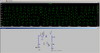
It's a single count from a photo-interrupter, and the gear in question is small and made of plastic. I did try sticking an optical disk on it but it didn't make any difference. Maybe it wasn't contrastey enough. The interrupter is mounted with an adjusting screw to get the best signal. The geartooth wave goes into a p-mos (bss84) which turns it into a slowish rise/fall pulse. An extra signal gets switched in when the direction needs to change, which overrides the pulse input and tells the digital pot that it's feeding into to change direction. The direction signal is open circuit when receiving pulse input. A couple of small caps set up the necessary delay for this control pulse. Then it all goes into an NPN as the output device to drive the pot.

The digital pot is.... (checks data sheet) oooohhh hang on, rising edge makes it go up, falling edge makes it go down, which is exactly what I want to happen anyway. I thought it was falling only. I designed this thing seven years ago and then shelved it after the initial build highlighted this exact problem. I'm still re-learning how it works!

So I'm chasing a red herring with this phase reversal. It was the difference in up/down pulse counts that got me onto it but it's just plain the wrong idea. Would explain why doing it actually made the problem much worse!

I think the extra signal in this experiment was just due to flakey breadboard assembly. I got it clean since writing but the pulse counts are still off.

I found part of the problem was due to vibration, also there's a little bounce (hard to spot) at the end of travel. But it doesn't explain everything.

Anyway, it did occur to me to add a second photo-interrupter as a kind of compensation,, but I'm really not sure what I'd be doing with it... I'm almost at the point of replacing the optical system with a mechanical pot, but that would make me sad :(
 
What digital pot is it?
The only ones I can find that work from logic signals have separate direction and clock inputs, or separate up and down count inputs.

Do you have a schmitt trigger between the input transistor and the digipot count pin, to avoid oscillations during a slow transition?
 
MCP4011. The direction changes depending on the status of the up/down pin when chip select goes low.

Huh, now I've looked at the datasheet a bit more I see it does only change position on the rising edges. I was looking at the wrong section earlier... So the phase change appears to be needed after all, unless I'm being really dumb (which would be no surprise).

I chose that particular pot mainly for reasons of cost and it being a device I could buy in a hobbyist sized quantity from RS. There are more suitable ones but I was very poor at time. Using it just made the circuit a bit more complicated.

No I don't. It seemed to work ok with just the open-loop NPN output. Looks quite good in simulation, not so much IRL. When I first went back to it I found evidence I'd been expermenting with positive feedback in the signal conditioner, however it seems fine without it. At the moment it's got an old audio 2sc-something. It'll look better with a faster tranny in there I know.

Would oscillation
a) be visible when I probe the chips up/down input with (my 50yo) scope? I've seen the output going up and down nicely with the input pulses whilst it's doing it's wrong thing.
b) cause the problem I'm having? I'd have thought it would lead to really wild value changes.

But I've a strong feeling it's down to the logic of the actual input pulses and how they relate to everything else, both electronic and mechanical.

Anyway I've got 7 days at work ahead of me so not much chance to tinker with it.
 
MCP4011. The direction changes depending on the status of the up/down pin when chip select goes low.
Wow.. That uses the weirdest and nastiest control protocol imaginable...

I'd chuck it away and use a more conventional type that has separate direction and count inputs, it should be vastly simpler and more reliable!
eg. a DS1804 should do it:

Re. oscillation, it could be a totally internal effect if the pin voltage takes too long to transition between the maximum low and minimum high voltages & it's not got a schmitt trigger input. If it's marginally just too slow you could get occasional single extra counts.

Though looking at that device data, getting it to work at all with anything other than an MCU controlling it looks to have been a new miracle!
 
Last edited:
Yes it would definitely mean I could downgrade from "ridiculously complicated" to "overly complicated". However also more than I'd like to spend. At the end of the day, this is only an automated PCB drill built mainly from scrap and stuff I already had.

It actually proved very easy to control. I got a 1/2 556 monostable (the other half does pwm) to trigger on either kind of state change of one of the flip-flops, so it produces the chip-select pulse on every direction change. The pulse turns on 1/4 of a 4066 which gets it's input from the other flip-flop, so the other side of that produces a high or low pulse, or open circuit. That feeds into the middle of the input pulse conditioner, so if it's high or low it swamps the input pulses from the bss84 (also get somewhat blocked at the input), if it's open they get through. There are a couple of small caps in there to create a delay. The chip-select pulse is connected directly to the pot and the other one becomes an alternative to the opto pulses. When the chip-select pulse finishes, the up/down input is still being held high or low by the small caps,. so it performs the direction change.

A micro would probably have been simpler, but when I designed this thing I didn't have a clue how to actually use one, and now I've gone back to it I've been enjoying getting it working again. But for this one last issue, which is driving me potty.

I will try putting a Schmidt trigger in there and see if it behaves, but I have a feeling it won't. The pulses could definitely do with speeding up.

I also thought about having the input pulses trigger a monostable instead of going directly through, but have been too tired to bother working out what would actually happen there. Also another chip to add, which is something I want to avoid.
 
Hah! Figured it out. If the input from the opto is high at the time the digi pot gets it's change to the down direction signal, when the control pulse finishes it causes a false rising edge input, causing it to adjust 1 step. Vibration and bounce does the rest. Hence the very gradual, inconsistent and somewhat "tunable" nature of the problem.

So it looks like a monostable is what I need, so the input is always low when at rest.
 
Status
Not open for further replies.

Latest threads

New Articles From Microcontroller Tips

Back
Top