Continue to Site

Welcome to our site!

Electro Tech is an online community (with over 170,000 members) who enjoy talking about and building electronic circuits, projects and gadgets. To participate you need to register. Registration is free. Click here to register now.

  • Welcome to our site! Electro Tech is an online community (with over 170,000 members) who enjoy talking about and building electronic circuits, projects and gadgets. To participate you need to register. Registration is free. Click here to register now.

Crowbar With a Fet Conundrum

Status
Not open for further replies.

ACharnley

Member
Hi,

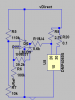
I'm applying a crowbar using a FET. The idea is to "push" the voltage back to the source rather than "burn" it off with resistance. The circuit below simulates and works correctly however there's no hysteresis to prevent the FET rapidly cycling (so in effect it is "burning" the voltage as resistance during the switch state).

Slowing it down using a small capacitor across R7 works to some extent but makes the crowbar voltage level frequency dependent. It currently turns on at 30V and turns off at 30V and therein lies the problem - it's relying on the op-amp and FET switch speed. I need it to turn off at say 10V, a 20V drop (anything higher than 8.5V as there's minimal capacitance after that). You can see as it stands the LM393 and FET on/off time results in a 8V drop. The TO-220 is getting HOT!

Any ideas? I suppose I could solve it using another op-amp but I'm now space critical on the design!

Regards,

Andrew

Screenshot_2018-08-29_17-05-55.png

Screenshot_2018-08-29_17-07-15.png

hammeer.png
 
Last edited:
Yes, forget the application of it, just this particular problem. The source is current limited and will collapse (good!).
 
Played around and sorted it!
 

Attachments

  • Screenshot_2018-08-29_18-57-48.png
    Screenshot_2018-08-29_18-57-48.png
    11.2 KB · Views: 121
  • Screenshot_2018-08-29_18-57-20.png
    Screenshot_2018-08-29_18-57-20.png
    9.6 KB · Views: 126
Yes.
Adding hysteresis by positive feedback around the comparator is the right way to fix this problem.
 
In spice a voltage source can have millions of amps of output. Shorting it out .... is not like real life. You can have a voltage source with 10 ohms.

Most CrowBar circuits collapse the power supply. When the LM339 dose not have a good supply it can not turn on a MOSFET.
Adding positive feedback really helps but the LM339 must have some voltage to run on. There needs to be enough voltage to turn on the MOSFET.

I your first post:
When the supply gets too high the LM339 turns on the MOSFET which loads down the supply which causes the LM339 to turn off the MOSFET. This is known as oscillation. Parts get hot. Positive feed back can latch the LM339 on. Once on all wise on until you turn off the power and restart.
-------------edited-------
https://en.wikipedia.org/wiki/Crowbar_(circuit)
Many crowbar circuits use a SCR or Triac because they latch on and stay on.
 
Hi Ron,

I exhausted the triac method but I have a highly inductive power supply. Even tried ST's ACS "stubberless" triacs but all to no avail.

I'm not collapsing the power supply completely, there's a bank of super-caps and if it goes below the 10V mark they'll turn on and short through the FET. Then it will get _hot_.

I've modelled the supply in spice and it's performing quite like the real thing, circa 20% error. A data logger allows me to view the real thing and since it's low frequency the LM339 / FET is able to turn on/off fast enough.
 
Hysteresis is a good idea.
If you still have issues consideration could be made around R5 & R7, when the fet turns on & draws current, voltage going in to the top of R5 & R7 will probably drop causing oscillation.
If its an Smps can you 'fiddle' with the feedback & reduce the pulse width by sensing current with an op amp.
 
It's supposed to drop, there's always going to be some measure of oscillation (so some measure of heat build up). The approach is to make it voltage/frequency dependant not Op-amp/FET switch-speed dependant. If it proves successful switching should be about 1/5 (so says LTSpice, I have yet another PCB prototype on the way to verify it).

It's a highly inductive source with a high impedance (about 3 ohm). I have to be careful though if the voltage drops too much the super-caps will engage and at that point there'll be a fire!
 
Status
Not open for further replies.

Latest threads

New Articles From Microcontroller Tips

Back
Top