Electro Tech is an online community (with over 170,000 members) who enjoy talking about and building electronic circuits, projects and gadgets. To participate you need to register. Registration is free. Click here to register now.
Welcome to our site! Electro Tech is an online community (with over 170,000 members) who enjoy talking about and building electronic circuits, projects and gadgets. To participate you need to register. Registration is free. Click here to register now.
Hello!
I have a XC95144 and 27c256
I want to write (by VHDL) program:
Access data from eeprom and move this data into CPLD, then I move them to I/O pin to drive led
I want your helping!!
Thanks
Hi
You need to write a 14 bit counter program for the addressing the EPROM and an 8 bit buffer for the data outputs of the EPROM and extra 2 buffer program to control CS and OE of the EPROM
--I have write this program, but i think it is wrong
--Declare library
......
--entity
entity counter is
port(clk,rst: in std_logic;
add: out std_logic_vector(14 downto 0);--address of eeprom
data: in std_logic_vector(7 downto 0);--data of eeprom
display: out std_logic_vector(7 downto 0);--display data of eeprom to check
);
end couter;
------------------------------------------
architecture counter of counter is
begin
process(clk,rst)
variable v:=std_logic_vector(14 downto 0):="000000000000000";
begin
if (rst='1') then
v:="000000000000000";
else
if (clk='1') and (clk'event) then
if (v=65535) then
v:="000000000000000";
else
v:=v+1;
end if;
end if;
end if;
add<=v;
display<data;--receive data from eeprom to display with led
end process;
end counter;
Hi
Yes it is right to connect the CE and OE to GND
I review your program and correct It and her is the corrected program
--entity
entity counter is
port(clk,rst: in std_logic;
add: out std_logic_vector(14 downto 0);--address of eeprom
data: in std_logic_vector(7 downto 0);--data of eeprom
display: out std_logic_vector(7 downto 0);--display data of eeprom to check
);
end couter;
------------------------------------------
architecture counter of counter is
begin
process(clk,rst)
variable v:=std_logic_vector(14 downto 0):="00000000000000";
begin
if (rst='1') then
v:="00000000000000";
else
if (clk='1') and (clk'event) then
v:=v+1;
end if;
end if;
add<=v;
display<data;--receive data from eeprom to display with led
end process;
end counter;
Thanks!
Now, i want to take data from EEPROM, but i don't display it. I want to display each bit of byte.Example, if i receive a byte="11010101", i want to display bit0='1',bit1='0', bit2='1' and so on, serially.
But i don't know.
Can you help me more?
Thank again.
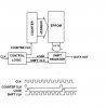
In order to display the data of the EPROM serially you need a shift register with parallel load to load the data of the EPROM in and a control logic circuit to generate the load pulse for the shift register , address counter CLK and shift register clk . The attached figure shows a block diagram and timing diagram of the system
Hi
Try to write VHDL program for each module of block diagram separately and create a schematic block for it and after that use the schematic editor to interconnect the blocks. Now you have the code for the counter and the buffer try to create a schematic block for them. Use the same procedure to write a VHDL module for the shift register and the control logic module and i will help you
Hi
Try to write VHDL program for each module of block diagram separately and create a schematic block for it and after that use the schematic editor to
Kamal daniel
you know, I had to do the same thing and I had no clue of FPGA programming but after reading the net for few hours, and looking at Verilog sample code I could wipe out a pretty usable code in Quartus - I was working with Altera dev.board so I had to use their free Quartus IDE and I kinda liked it
Following is VHDL code for an 8-bit shift-left register with a positive-edge clock, asynchronous parallel load, and serial out.
library ieee;
use ieee.std_logic_1164.all;
entity shift is
port(CLK, ALOAD : in std_logic;
D : in std_logic_vector(7 downto 0);
SO : out std_logic);
end shift;
architecture archi of shift is
signal tmp: std_logic_vector(7 downto 0);
begin
process (C, ALOAD, D)
begin
if (ALOAD='1') then
tmp <= D;
elsif (CLK'event and CLK='1') then
tmp <= tmp(6 downto 0) & '0';
end if;
end process;
SO <= tmp(7);
end archi;
I want to use CPLD (in VHDL) to scan matrix led.
But I don't know. Can you post for a simple example: display "A" character in a matrix led 8x8
Thanks a lot!
It can't be done by CPLD alone you need a memory (EPROM) to store the character data in . I suggest you design it from standard IC first and then implement it in VHDL
yes, i use a EEPROM to store data, then I use cpld to take them. I use 6B595 to shift data from CPLD. Finally, i want to display them on matrix led (8x8)
Can you help me again?
Thanks a lot.
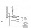
The attached figure shows the block diagram of a CPLD based 8x8 LED matrix display.The gray blocks of the figure must be written in VHDL.In this figure I'm using 8to1 multiplexer to convert parallel data of the EPROM to serial because it doesn't need any control signal. Also I'm using 3to8 line decoder as a column select. In the previous posts i send to you VHDL code of 14bit counter please modify it to 17bit counter as shown in the figure. The following is the VHDL code for the 8to1 multiplexer, 3to8 line decoder, and 3input AND gate
WITH sel SELECT
z<=d0 when "000",
d1 when "001",
d2 when "010",
d3 when "011",
d4 when "100",
d5 when "101",
d6 when "110",
d7 when "111",
'0' when others;
END behavior;
-----------------------------------
-- 3-to-8 decoder
library ieee ;
use ieee.std_logic_1164.all;
entity decoder is
port (
a, b, c : in std_logic ;
y : out std_logic_vector (7 downto 0) ) ;
end decoder ;
architecture behavior of decoder is
signal abc : std_logic_vector (2 downto 0) ;
begin
abc <= a & b & c ;
with abc select y <=
"00000001" when "000",
"00000010" when "001",
"00000100" when "010",
"00001000" when "011",
"00010000" when "100",
"00100000" when "101",
"01000000" when "110",
"10000000" when others ;
end behavior ;
-------------------------------------------------
-- 3 input AND gate
library ieee ;
use ieee.std_logic_1164.all;
entity and_gate is port (
a,b,c : in std_logic ;
d: out std_logic ) ;
end and_gate ;
architecture behavior of and_gate is
begin
d <= a and b and c ;
end behavior ;
This site uses cookies to help personalise content, tailor your experience and to keep you logged in if you register.
By continuing to use this site, you are consenting to our use of cookies.

")