Problem: I need to fool engine governor control module into thinking engine is running at 2200 RPM in lieu of the 2000 RPM pre-programmed setting. I need engine to maintain 1800 RPM at 60 hz for whole-house 20KW generator. Reason being this particular Governor control has PIC programmed RPM settings of 1350, 2000 and 2400 RPM. My engine is a Ford 4 cylinder gas LSG4231 with a Ford Dura spark module (white grommet). Got tired of having to hook up to tractor PTO and just opted for this permanent driver engine.
Idea: My idea is if the module pre- programming thinks engine is running at 2200 RPM in lieu of the preset 2000 RPM it will compensate by dropping off the 200 RPM needed to get to 1800 RPM 60hz area where I need to be. Also if there was a trim pot in this circuit I could fine tune this setting even better. I have schematics of original sweeper unit wiring this controller was originally designed for which is a big help in how this unit functions. I also have schematic of how the controller wires to engine module and actuator.
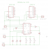
I am a newbie to electronics and my knowledge is limited. I have built variable psu, basic alarms, 555 timer tester, octopus tester among others. I own and love an ESR meter and have old CRT Oscilloscope I am still trying to learn. I read several other post here and came across a 555,4093,4017 decade circuit I think I am looking for to make this work. I am not looking for anyone to build my circuit for me but help me with the vast knowledge I see here. I want to learn how these IC’s function and what they can do. I just need a start in the right direction.Thanks
Idea: My idea is if the module pre- programming thinks engine is running at 2200 RPM in lieu of the preset 2000 RPM it will compensate by dropping off the 200 RPM needed to get to 1800 RPM 60hz area where I need to be. Also if there was a trim pot in this circuit I could fine tune this setting even better. I have schematics of original sweeper unit wiring this controller was originally designed for which is a big help in how this unit functions. I also have schematic of how the controller wires to engine module and actuator.
I am a newbie to electronics and my knowledge is limited. I have built variable psu, basic alarms, 555 timer tester, octopus tester among others. I own and love an ESR meter and have old CRT Oscilloscope I am still trying to learn. I read several other post here and came across a 555,4093,4017 decade circuit I think I am looking for to make this work. I am not looking for anyone to build my circuit for me but help me with the vast knowledge I see here. I want to learn how these IC’s function and what they can do. I just need a start in the right direction.Thanks
 Thanks for catching that.
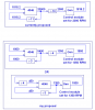
  So you set the VCO to a nominal 600Hz. Divide by 10 for the VCO comparator and divide by 9 for the governor.

") haha I am gonna set up a blog which will be more useful for this type info.BTW how do I post the PDF's here? I got album set up for pics already on this fourm under my name.BTW I have a slew of resistors already,what range supply of electrolytic caps should I order.. I have good supply of disc.style non-polarity style already.Also should I run this circuit though a 7812 Volt reg.first? Thanks to all of you for your help.Got the boat off Lake Erie and winterized and firewood split so should have more time for some of these fun projects.
haha I am gonna set up a blog which will be more useful for this type info.BTW how do I post the PDF's here? I got album set up for pics already on this fourm under my name.BTW I have a slew of resistors already,what range supply of electrolytic caps should I order.. I have good supply of disc.style non-polarity style already.Also should I run this circuit though a 7812 Volt reg.first? Thanks to all of you for your help.Got the boat off Lake Erie and winterized and firewood split so should have more time for some of these fun projects. . If I didn't already have stock, I would be tempted to get Night Fire Electronics "Aluminum Electrolytic Capacitor Axial-Only Kit #3" from their ebay site. (nfceramics). The current listing is item 220241753729. Saves a lot of picking around for just $14.
")