Electro Tech is an online community (with over 170,000 members) who enjoy talking about and building electronic circuits, projects and gadgets. To participate you need to register. Registration is free. Click here to register now.
Welcome to our site! Electro Tech is an online community (with over 170,000 members) who enjoy talking about and building electronic circuits, projects and gadgets. To participate you need to register. Registration is free. Click here to register now.
Using this method there is still 28V on the pin but there is only a very small amount of current and the PIC will clamp it to 5V. By ohms law the very small current results is almost no voltage drop across the resistor. The resistor is there to protect the PIC should the pin be set as an output. it limits current.
A voltage divider is more useful when we need to scale a voltage prior to reading it with a ADC.
Using this method there is still 28V on the pin but there is only a very small amount of current and the PIC will clamp it to 5V. By ohms law the very small current results is almost no voltage drop across the resistor. The resistor is there to protect the PIC should the pin be set as an output. it limits current.
Nigel Goodwin I'm with you I would use what works best but in light of what has been posted at microchips forum and what i have read
I 'm going to be a little more careful about telling some one to poke 28 volts on a input pin. There a lot of room for mistake's.
With a voltage divider they can't go wrong telling them to use a current limiting resistor they could pick the wrong pin
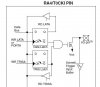
This one I/O pin has protection diode to VSS only.
Nigel Goodwin I'm with you I would use what works best but in light of what has been posted at microchips forum and what i have read
I 'm going to be a little more careful about telling some one to poke 28 volts on a input pin. There a lot of room for mistake's.
If someone is going to make mistakes as idiotic as that, then a potential divider isn't going to help
To place 28V directly on the pin you would need to not use a resistor at all (just a piece of wire), using the same 'piece of wire' as the top resistor in a potential divider would have EXACTLY the same effect.
With a voltage divider they can't go wrong telling them to use a current limiting resistor they could pick the wrong pin
This one I/O pin has protection diode to VSS only.
RA4 would be a stupid pin to choose, as it's the only open-collector pin there is, and can be used to switch higher voltages than Vdd (hence you can't have a protection diode).
I've also repeatedly mentioned the alternative of using a potential divider in this thread, but the fact remains, it's NOT actually required.
Ok just past the green part saying the pin was at 28V I said it was clamped to 5V. I was trying to say that the resistor is not responsible for the voltage drop. It is due to the diode clamp. Did a insert explicative poor job.
By ohms law the very small current results is almost no voltage drop across the resistor.
I will flat out give you this one. I was only thinking of the resistor as a current limiting. I can see that the voltage drop, forced by the Zener, is important to the survival of the Zener.
The voltage divider is looking better to me, just one more resistor and we do not have to rely on the Zener clamp.
I like the voltage divider for the preferred suggestion to beginners.
It has safety benefits and an added benefit that it can be built and tested with 2 resistors (to test output voltage levels) WITHOUT needing the PIC connected. So the "scary testing" bit can be done with no risk to the PIC.
And I also like putting caps on input pins, but maybe that's a more commercial approach than a hobby approach?
I have posted more the a handful of examples doing zero crossing with just a resistor but after arguing this with a bunch of people.
There just too many thing that can go wrong
I like this thanks MrRB
It has safety benefits and an added benefit that it can be built and tested with 2 resistors (to test output voltage levels) WITHOUT needing the PIC connected. So the "scary testing" bit can be done with no risk to the PIC.
I will flat out give you this one. I was only thinking of the resistor as a current limiting. I can see that the voltage drop, forced by the Zener, is important to the survival of the Zener.
The voltage divider is looking better to me, just one more resistor and we do not have to rely on the Zener clamp.
Not necessarily. In many (most?) applications you know what the minimum period of the input will be, so I add a cap of a value that allows that pulse voltage to just reach from rail to rail. Usually I am testing on the scope so I just hold a few assorted caps from the input pin to ground and look at the waveform.
Then once the cap is installed it has a very high rejection of noise spikes etc, things like digital edge switching spikes etc in the nS to uS range that might cause false triggering. There is no need to have the ability to respond to signals faster than the fastest "real" signal.
This site uses cookies to help personalise content, tailor your experience and to keep you logged in if you register.
By continuing to use this site, you are consenting to our use of cookies.