Continue to Site

Welcome to our site!

Electro Tech is an online community (with over 170,000 members) who enjoy talking about and building electronic circuits, projects and gadgets. To participate you need to register. Registration is free. Click here to register now.

  • Welcome to our site! Electro Tech is an online community (with over 170,000 members) who enjoy talking about and building electronic circuits, projects and gadgets. To participate you need to register. Registration is free. Click here to register now.

Conventional current or standard flow?

Status
Not open for further replies.

billybob

Active Member
As the title suggest, I am trying to decide what are the differences in reading a schematic with Conventional current flow vs Standard. I have trouble understanding exactly how a circuit works in a schematic I useually follow the positive terminal into where there is least resistance and try to figure it out from there. Am I doing this wrong? Is there a better way to understand and learn to read schematics?
Thank you in advance,
Ben
 
It's a circuit either way, just look at whichever possible paths make the most sense.

You do need to consider the possible low current control control paths as well as high current paths, though.
 
Take a look here. https://www.mi.mun.ca/users/cchaulk/eltk1100/ivse/ivse.htm
The signal in Schematics' in N.A. at least are typically seen to flow from left to right, and top downward. i.e. conventional flow.
I grew up in the valve/tube era, so initially I learned the electron flow version as it made more sense in valve technology.
With the advent of semi conductors, it was less obvious and also most now use the conventional flow method.
 
What about in a circuit like this. According to conventional current flow I follow VCC across the top connectors at what point does the current (decide) to start filling C2? Or C3? Or just making a big loop and fill C4 and 5? Or does it go through R1 how do I find which is first when in an oscillator circuit such as this it is important to know.
1617294823323.png
 
Voltage is imposed across C1 reservoir capacitor , C2 & C3 are DE-coupling caps, all with power applied at power on.
, R1 is just a voltage divider for RP1, the inductors and capacitors C4,C5 etc appear to be part of the oscillator circuit and will oscillate at the resonant frequency of the oscillator.
 
In my opinion, there's no need to ever consider either - and originally of course electron flow was never considered at all, it was all about current flow.

You've then got the added confusion of positive and negative supply rails etc. including negative at the top.

I simply consider current flows from top of the diagram to the bottom, everything works perfectly, and there's no confusion - and it's just 'current flow'
I think I follow what your saying, but how would this even induce a current through L2? (I know I’m getting a little off topic, but I don’t want to make a new thread.) As soon as the drain and source are closed L1 gets all the current.
 
You need to explore the world of tuned circuits, filters and oscillators! ;)
Well I’m trying to find people on YouTube that will go through schematics and the different steps so I can learn, because I’m pretty visual when it comes to that stuff. I do have a book “How to diagnose and fix everything electronic” that has a few problems he goes through which really help. Unfortunately I can’t find anymore elsewher.
 
at what point does the current (decide) to start filling C2? Or C3?
For the initial DC condition, consider it to flow everywhere at the same time.

Remember that capacitors in series act as a divider when they charge or discharge, like two resistors in series; small cap like a high value and large cap like a low value. Most of the voltage will be across C4 to start with, then C3 will charge to the voltage set by the resistors.

With that circuit, I'd then think about the change in voltage across the transformer windings as the transistor switches on or off, and how that change affects the rest of the circuit.
 
Alright I think I understand the main idea here. Correct me if I’m wrong. C4 and C5 start charging at power on and once the point between these two capacitors reaches a certain (positive) or (negative) voltage I’m not sure which one. The mosfet switches on because of the specific tuning as a result of the potentiometer and R1. Therefore connecting the secondary to ground and discharging C4 and 5 through the primary. From what I see the mosfet acts like the spark gap of sorts.
 
Therefore connecting the secondary to ground and discharging C4 and 5 through the primary. From what I see the mosfet acts like the spark gap of sorts.

In a way. The transformer windings couple the changes in drain current, the varying voltage across L1, to L2 and L3.
Those in turn modulate the gate voltage and provide the circuit output.

This oscillator may be easier to understand. The coil is two windings in phase, or one winding with a tap in the centre whichever way you want to look at it.
Like a centre tapped mains transformer secondary, if one end goes (or is forced) positive compared to the centre, the other end goes negative; and vice versa.

If the transistor starts to turn on and the voltage at its collector changes toward negative, making the right hand end of the coil do the same via C2, the left hand end goes positive and that couples to the base via C1, making the transistor turn on harder.
That accelerates the turn on and the collector going negative, until there is no more change.

At that, the voltage across the coil windings starts to drop - making the base go towards negative and turning the transistor off; which makes the collector go towards positive, with the right hand end of the coil following it & making the left hand end go more negative, again until the voltage limits are reached.

The capacitor across the coil resonates it and sets the working frequency, also giving a smoother waveform rather than just a square wave.

It's a bit like one end of a two transistor "multivibrator", but with the coil (actually a tuned circuit) being used to invert the signal before its fed back to the base, rather than another transistor providing the inversion.

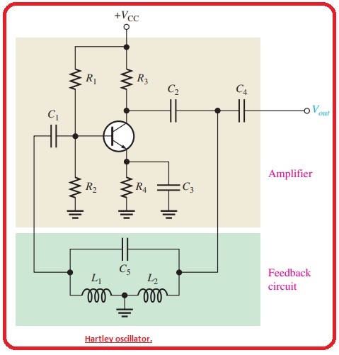
Hartley-oscillator..jpg
 
Thank you all for the help. I have done a little research on Hartly oscillators and am beginning to understand as you can probably tell I try to understand the schematic before I dive into the circuit. I'm sure you will see more like this later on!
 
You might enjoy this Big Clive video talking about Royer oscillators and high voltage generation.

 
Hola billybob

As a basically self taught person in these matters, I was lucky (or clever enough?) to go the conventional way since the beginning.

Happy to see the waste of time and confusion I avoided. Move on.
 
Status
Not open for further replies.

Latest threads

New Articles From Microcontroller Tips

Back
Top