Continue to Site

Welcome to our site!

Electro Tech is an online community (with over 170,000 members) who enjoy talking about and building electronic circuits, projects and gadgets. To participate you need to register. Registration is free. Click here to register now.

  • Welcome to our site! Electro Tech is an online community (with over 170,000 members) who enjoy talking about and building electronic circuits, projects and gadgets. To participate you need to register. Registration is free. Click here to register now.

controlling back EMF on a model railway DCC accesory decoder .

Status
Not open for further replies.

garyd

Member
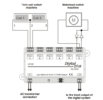
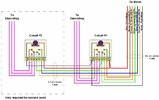
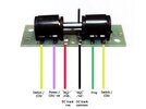
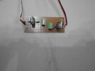
Hi , I am trying with limited electronics knowledge to complete a model railway almost completed by my late father , it is DCC and computer controlled via windows based software ( RR&Co)and I only have one thing left to complete in that the layout incorporates 2 Electromagnetic uncouplers which are just simple single coil devices that produce a magnetic field to lift a coupler on a railway wagon or carriage and so enable seperation of said wagons automatically , I propose to do this via a Lenz LS150 DCC accessory decoder utilising just 2 of it's 6 outputs , the outputs for twin coil points/switches are of no use to me as they use 3 wires but they can be converted to 2 wire output by the use of 2 diodes per output ( see attached diagram ) I am worried that the flyback voltage generated when an uncoupler is de energised will damage the circuitry of the LS 150 but am wondering if the the 2 diodes used to allow 2 wire output will give the necessary protection ? , I have tried on model railway forums to get a definitive answer but have so far got almost nowhere .
 

Attachments

  • Screenshot 2021-08-27 at 21-39-33 Lenz-LS150-Manual - DCCconcepts.png
    Screenshot 2021-08-27 at 21-39-33 Lenz-LS150-Manual - DCCconcepts.png
    25.3 KB · Views: 276
No, a series diode will not help; just add a diode in parallel with the uncoupler coil, arranged so it does not conduct on the normal polarity.

If each half of the output can be controled separately, you may be able to use a single output for two uncouplers? Connect each in series with a diode, rather than in series with the common junction of the two diodes; eg. the diodes from the motor side of the diagram, but separately feeding two solenoids, as in the left side of the diagram.
 
I've modded the drawing to show what I mean:
(Edit - there should be a junction dot at the crossover next to the "2"; the two diodes connect directly across each coil).

Lenz-LS150-mod.jpg
 
Hi rjenkinsgb thanks for the reply , i'm pretty sure that the 2 coils you show cannot be controlled seperately by the LS150 and I have no need to go that way as the LS150 is dedicated to this one task and i'm not bothered by the fact that 4 outputs will remain unused , the layout uses Lenz LS100 accessory decoders for switching points/switches via motorised switch machines because they unlike the LS150 have feedback as to the motors position these also have 3 wire output but can be converted to 2 wire by the use of individual adaptor boards fitted to each output ( these boards cannot be used with a LS150 ).I would much prefer to use the 2 output approach as it makes it easy for the DCC digital system to see them as each can be given an address which is also what the control software will see .I assume that I should put a diode IN4001 as I have some in parallel across the 2 wires attached to the uncoupler ? does it matter which way around ? ie silver band end to red or black uncoupler wire .Btw I have included a Diagram of a LS100/110 showing one of the adaptor boards to convert to 2 wire output purely for the sake of interest as it's not really relevant to what we are discussing .
 

Attachments

  • 11010.gif
    11010.gif
    4.7 KB · Views: 234
That adapter is shown driving a motor, so presumably it's just the two diode circuit at the right of your original drawing & will ouput both polarities.
You would still need both a series diode to control which polarity it switched on if feeding a solenoid, plus the parallel diode to protect from back EMF.

Just duplicate one half (left or right) of the circuit I posted & use it on two different outputs, that should be the simplest approach.

The diode polarities relative to each other are critical; they must have the same end to the wire they both connect to, and teh approriate way as drawn depending if you use the lefty or right terminal.

As drawn, the positive of the uncoupler is to the right in each coil position, which is the band end of the parallel flywheel diode.
 
I'afraid you are losing me as I find electrical schematics hard to follow , could you please just show the full circuit including all diodes for one output plus the 2 wire uncoupler and then I can probably get my mind around it ?.
 
I'afraid you are losing me as I find electrical schematics hard to follow , could you please just show the full circuit including all diodes for one output plus the 2 wire uncoupler and then I can probably get my mind around it ?.
Is the switch machine motor also drive by changing the voltage polarity?
 
Thank you I get your meaning now so just 2 diodes still but wired differently so that the centre terminal and the right side terminal are now used , i've just realised something that I should have mentioned earlier in that the LS 150 uses 16 V AC for it's input and outputs approx 15 V AC i'm not sure if that makes a difference ? , as for changing polarity I don't know .
 
I've found 2 diagrams showing a Solenoid switch machine and a Motorised switch machine with the first one being the same model of motor that the layout uses , I hope this helps .
 

Attachments

  • Point_wiring.jpg
    Point_wiring.jpg
    108.7 KB · Views: 229
  • images.jpg
    images.jpg
    5.8 KB · Views: 223
the LS 150 uses 16 V AC for it's input and outputs approx 15 V AC
That will be why a diode is needed at each output, for things than need a fixed polarity. The direction of teh diode sets what polarity passes through.

Most of the connections on the switch machines relate to the auxiliary contacts in the devices; the control wiring is just two or three wires, as in very the first image you posted.
 
I think I can now proceed and see how I get on , the LS 150 will need addressing and it's output which is pulsed will need to be programmed to give a 3 second pulse which should raise the coupler for sufficient time for a Loco to pull away , i'm awating the arrival later this coming week of a Solenoid switch machine which is needed to to set the LS150's address as there must be a load on the number 1 terminal block for the programming to work and it only works if you use a solenoid switch machine and not a motor switch machine and I have no idea as to why , when i've done that i'll try it out and come back here and let you know .
 
Hi , as promised i'm back after setting the LS150 up but have encountered a problem in that there appears to be insufficient voltage to fire an uncoupler strongly enough , I have read that the LS150's output voltage is much reduced from it's 15 volts output when diodes are used so i've had an idea , in dads electrickery box of bits and bobs there is a small circuit board that apparently can convert 14-24 volt AC to 12 volt DC so I thought that I could maybe use this to convert the LS 150's 15 volts? AC to 12 volt DC and then use 2 of the boards 3 X 12 volt outputs to fire 2 relays which would be supplied with 18 volt DC from a seperate regulated psu , there is some discussion I found on google that states that these uncouplers need 18 volts and work much better with DC rather than AC , i'd welcome your thoughts .
 
The setup with a single diode that the makers show only gives half-wave DC so the average is half the AC voltage (but plus some "flywheel" effect via the parallel diode),

If you used a bridge rectifier instead, it would be full wave and the same average voltage as the AC supply.

Adding a capacitor across the uncoupler with either circuit will drastically increase the voltage; eg. 1000uF 35V or higher.
That will increase the DC to roughly 1.4 * the AC voltage, so near 18V for 12V AC input.
 
I see , so i'll need a bridge rectifier what spec should I go for ? i'll need to get one , the capacitor is no problem as dad had a whole selection of them and one is a 45 volt 1000uF , what would the circuit look like ? and could I mount it all on some veroboard ?.
 
I should have mentioned that in the discussion I saw there was some disagreement as to the amps drawn by the uncoupler or rather a single one , some said they drew around 1 amp whilst others reckoned they had measured 1.5 .
 
If you just connect the capacitor straight across the uncoupler coil to start with, keeping the same two diodes & see if that works?
Capacitor positive to the diode cathode (banded) end.

The current will depend on the supply voltage, but if it does take more than one amp you will need a bridge rec as a single 1N4000 series diode can't handle more than an amp.
 
It seems that the capacitor is faulty ( it does look old and used) so i've ordered 2 that should be here by Wednesday , I have another challenge for you in the meantime though in that do you think the item in the attached pic is a leftover self made board that my dad made to control the uncouplers via an Arduino ? ( his friend thinks so ) dad abandoned that route when he realised that it would involve coding as he had an aversion to that .
 

Attachments

  • DSC00101.JPG
    DSC00101.JPG
    122.9 KB · Views: 213
I should of course have listed the components which apart from the 2 terminal blocks consists of a blue resistor with bands brown brown black black brown which I think is a 110.00 ohms the next thing is what I think is a mosfet and it has JDP TIP 120 1603 printed on it and lastly there is an IN40001 diode .
 
It does sound like a power switch to operate from an MCU or other logic level output. You don't need it for the DCC module though.
 
Status
Not open for further replies.

Latest threads

New Articles From Microcontroller Tips

Back
Top