Continue to Site

Welcome to our site!

Electro Tech is an online community (with over 170,000 members) who enjoy talking about and building electronic circuits, projects and gadgets. To participate you need to register. Registration is free. Click here to register now.

  • Welcome to our site! Electro Tech is an online community (with over 170,000 members) who enjoy talking about and building electronic circuits, projects and gadgets. To participate you need to register. Registration is free. Click here to register now.

Control of Vout (HV Power Supply)

Status
Not open for further replies.
Just curious, using the MOSFET in series with the resistor, were you applying PWM pulses to the gate or DC derived by filtering the PWM? (The MOSFET is to be switched on and off with a digital signal.)
 
The diodes help in linearity behavior of the circuit. Regarding temp stability, I don't know. Will have to test it.

Also soon I'll test another one, the attached. Looks promising. Have to make some calculation first.
 

Attachments

  • High voltage power supply opamp.png
    High voltage power supply opamp.png
    6.3 KB · Views: 89
OK, test on the above circuit was good based on LM358 chip because I could not handle the tiny OPA one. It worked very good on the PWM signal with good regulation.

Now I would like to add a current limir because the MOSFET cannot handle over 500mA and burns instantly, although I selected a FQP4P40 one that say can accept up to 3,5A being a 400V transistor.

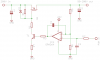
The scheme I tried muted the MOSFET and is not working at all, as it seems to short the G-S! Tried either NPN or PNP configuration but even with no load current the MOSFET stays off. Can anyone please explain why is that happening?

Thanks
Ioannis
 

Attachments

  • NPN_cl.png
    NPN_cl.png
    8.6 KB · Views: 89
  • PNP_cl.png
    PNP_cl.png
    8.6 KB · Views: 140
This one should work. The other one will not.
The current limit transistor will need to handle the 1mA coming from T1.
pnp_cl-png.113509

The little current limit transistor needs a base resistor. Maybe 100 ohms. If the current is TOO large the current (amps) will flow B-E and kill the transistor. Adding 100 ohms will keep the "amps" going through the 1.5 resistor and only a small amount of current B-E.
 
Thanks for the reply. Unfortunately it does not work. It seems as if the PNP is shorting the Vgs of the MOSFET even with no load current at all. Disconnecting the collector from the Gate works OK.

So it seems as there is a leakage current, enough to stop MOSFET from operating. Have replaced many transistors but all do the same thing...

It drives me crazy! Such a trivial thing...

Ioannis
 
Place a small load on the output. Maybe a 1 watt resistor. Right now you only have 300k of load.
 
No go either. The pass MOSFET is cut off as long as the small PNP or NPN is connected across G-S. When collector of this transistor is disconnected it works as expected.

Ioannis
 
Status
Not open for further replies.

Latest threads

New Articles From Microcontroller Tips

Back
Top