Continue to Site

Welcome to our site!

Electro Tech is an online community (with over 170,000 members) who enjoy talking about and building electronic circuits, projects and gadgets. To participate you need to register. Registration is free. Click here to register now.

  • Welcome to our site! Electro Tech is an online community (with over 170,000 members) who enjoy talking about and building electronic circuits, projects and gadgets. To participate you need to register. Registration is free. Click here to register now.

Constant Current Source (Again?)

Status
Not open for further replies.
hi Ron,
Its a pity that 'theo' started a new thread [with a totally different Title] on the same topic, it does cause duplication of work.

I didn't subscribe to the other thread so I didn't realise the previous work.;)

Eric
 
hi Ron,
Its a pity that 'theo' started a new thread [with a totally different Title] on the same topic, it does cause duplication of work.

I didn't subscribe to the other thread so I didn't realise the previous work.;)

Eric

Hi Eric, that is why I figured I would drop it in here. Thought it may help to see the origins. :)

Ron
 
Well, I accept your objection against starting a new thread for a same topic. That's why you have 11 nice glowing dots under your name that makes you excellent, while I've only one, a newbie! But ok, I expect within a year I'll have such glowing dots of experience, let me figure out the analog electronics in detail!

No, I did care it. Actually, I learned a lot like kelvin measurements and why a constant current source is preferred than a constant voltage when a very low resistance is measured from the previous thread. I closely followed ron's circuit (which he posted after a fun filled entertaining work day!!), and that helped me a lot to understand the CC mechanism.

Later, in a few days, I left my course's classical mechanics, and started figuring out the opamp basics from a book called Electronic Devices and Circuits, some web tutorials, some application notes and ron's and eric's circuit.

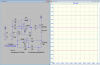
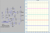
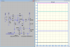
I've come up with the following circuit. I know the opamps need an upgrade to a better one. I've used 100mΩ sense resistor, so less voltage drop. The voltage source V2 for current adjustment should be replaced with some circuity+digipot. So, any suggestion about this CC?
 

Attachments

  • CCS1.png
    CCS1.png
    55.3 KB · Views: 159
  • CCMe.asc
    3 KB · Views: 133
  • CCS2.png
    CCS2.png
    52 KB · Views: 160
Last edited:
See it, I've replaces the V2 with a digipot using a resistive voltage divider.
 

Attachments

  • CCS3.png
    CCS3.png
    54.6 KB · Views: 132
hi theo,
Looks a suitable solution to the problem.
As you say a better OPA, and ensure a good heat sink for the FET
 
Please understand I wasn't objecting and would not discourage getting ideas from as many members as possible. Sometimes a new thread is well in order. It is a good idea to reference the old thread so those with new thoughts can see how things have evolved along. Anyway, starting with the basics you seem to have come up with a nice current source design. Have you actually bread boarded and tried it yet?

Ron
 
Thank you. In my previous design I used a high side current sense amp, and in this design, I don't have to use it. The first stage, ie. the non-inverting amp does it. What OPA will you recommend? I've not prototyped it on breadboard, but I'll do it around this week and show you the results. I had some N channel MOSFETs in my junk box, which I'll have to find.
 
Status
Not open for further replies.

New Articles From Microcontroller Tips

Back
Top