Continue to Site

Welcome to our site!

Electro Tech is an online community (with over 170,000 members) who enjoy talking about and building electronic circuits, projects and gadgets. To participate you need to register. Registration is free. Click here to register now.

  • Welcome to our site! Electro Tech is an online community (with over 170,000 members) who enjoy talking about and building electronic circuits, projects and gadgets. To participate you need to register. Registration is free. Click here to register now.

Constant current limiting with variable voltage?

Status
Not open for further replies.

king.oslo

New Member
Hello there,

I am building a power supply that will have variable current-limiting and variable output voltage.

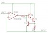
I am working on the current-limiting circuit. I read that I need a current sensing resistor, and a current limiting-transistor that limits the voltage to the base of the pass transistor.

When voltage across the current sensing resistor reaches 0.65V, the current limiting transistor starts to conduct voltage away from the pass transistor.

Using ohms law I found that the current sense resistance has to be a function of the output voltage of the PSU, to get the same current limiting across the entire voltage-range.

How can I get this variable current-sense voltage drop?

Thanks! :) M
 
Last edited:
Using ohms law I found that the current sense resistance has to be a function of the output voltage of the PSU, to get the same current limiting across the entire voltage-range.

How can I get this variable current-sense voltage drop?
I do not agree with you. Please post your schematic. (the part you have)
 
Here is an example of a current limit power supply.
When the voltage across R1 is 0.6 volts T3 turns on, this starves out T1, T2. The current limit is not a function of output voltage.
 

Attachments

  • ps.jpg
    ps.jpg
    15.5 KB · Views: 497
This is a pretty similar circuit to yours, it is the one I was looking at:

**broken link removed**

+Vcc 12V, Rsens 0.2ohm:
Vo will be near 0V when current is ca 60A

+Vcc 5V, Rsens 0.2ohm:
Vo will be near 0V when current is ca 25A

This is how I came to conclude that Rsens has to be a function of Vcc.

Please share with me your thoughts. What did I do wrong?

Thanks.

Kind regards,
Marius
 
Last edited:
Vo will be near 0V when current is ca 25A
Current will never get as much as 25A. As soon as the Q1 collector current rises to ~3A current-limiting kicks in: the voltage dropped across Rsens will be ~0.6V, so Q2 will begin to conduct, pulling down Q1 base and so preventing any further rise in Q1 collector current.
 
The base-emitter voltage of the sensing transistor changes when its temperature changes. Then the current-limiting current also changes when the temperature changes.
 
Status
Not open for further replies.

Latest threads

New Articles From Microcontroller Tips

Back
Top