Continue to Site

Welcome to our site!

Electro Tech is an online community (with over 170,000 members) who enjoy talking about and building electronic circuits, projects and gadgets. To participate you need to register. Registration is free. Click here to register now.

  • Welcome to our site! Electro Tech is an online community (with over 170,000 members) who enjoy talking about and building electronic circuits, projects and gadgets. To participate you need to register. Registration is free. Click here to register now.

Confused with P Channel MOSFET

Status
Not open for further replies.

electronist

New Member
Could anybody tell me which of Fig A or Fig B is the proper circuit.
The problem is that in Fig A the Battery supply is connected to Drain and in Fig B it is connected to Source.

Please help me out
 

Attachments

  • fig A.JPG
    fig A.JPG
    18.3 KB · Views: 283
  • fig B.JPG
    fig B.JPG
    10.6 KB · Views: 252
You need to show what's driving the gate in both cases.
Also, you have drawn an N-channel MOSFET.
 
P-FETS all the way.
 
He didn't ask if they were pfets, he was confused about which circuit works. But as ROFF said we can't answer the question till he explains what is supposed to be driving the gates.
 
Yeah, you guys are right, obviously.:eek:
They're PFETs. Once again, I posted before my coffee had soaked in.:D
 
As you can see from the diagram there is a pull up resistor, so if nothing else is driving then the gate is maintained at low or 0V. The other condition is a 5V supply being constant on the gate pin.

The question is Which of the two diagrams have the Drain and Source Pins rightly positioned?
 
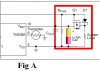
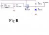
This appears to be a supply switchover circuit. The correct circuit has to be Fig. A. Assuming the 5V is capable of delivering more than a couple hundred milliamps, Fig. B will burn out D5, and then proceed to damage the battery through the body diode.
 
Status
Not open for further replies.

New Articles From Microcontroller Tips

Back
Top