Continue to Site

Welcome to our site!

Electro Tech is an online community (with over 170,000 members) who enjoy talking about and building electronic circuits, projects and gadgets. To participate you need to register. Registration is free. Click here to register now.

  • Welcome to our site! Electro Tech is an online community (with over 170,000 members) who enjoy talking about and building electronic circuits, projects and gadgets. To participate you need to register. Registration is free. Click here to register now.

Computer Power Supply Tester

Status
Not open for further replies.

Mike Jobe

New Member
I am looking to buy/build a computer power supply tester that loads the output with switched load resistors on each leg of the supply simultaneously. It needs to have volt and ammeters on each leg also (analog meters). The only testers on the market are led indicators that dont load the supply, only indicate a voltage present. The circuit needs to be inexpensive and a DIY project. Can anyone furnish a schematic with maybe a parts list??? Thanks
 
Please give us the data on the supply.
Example:
5 volt, 10A but I want to test it at 7A and
12V, 1A but tested at 0.5A etc.
Why analog meter? Do you have the meters now?
 
The tester should have a switched load on each leg..i.e. 5a, 6a, 7a, and so forth up to 30 amp, the same on the other legs>>12v, 5, 3.3v, and neg. outputs. I have the meters available, but would be receptive for a source of additional meters The tester would analyze supplies up to 750 watt and have capability to test AT and ATX supplies.
 
Hi,

For the high currents involved i would have to suggest using a shunt with meter, not a self contained meter.

Other than that, you'd have to get some power resistors and switches, that's about it.
 
12 volt supply:
12 ohm resistors = 1 amp, 12 watts. (a 12w resistor will be too hot at 12w so get 25 watt resistors)
I would solder the first resistor across the wires with no switch. (min load = 1A 12 watts)
Then add a bank of toggle switches. (maybe 10A) Each switch, switches in another 12 ohm resistor.
All switches off = 1A, 12W. One switch on = 2A, 24W. Three=3A, 36W..........

5 volt supply:
4.7 ohm or 5.0 ohm resistors, 5 watts (10 watt resistor)

3.3V supply:
3.3 or 3.0 ohm resistor, 3 watts (6 to 10 watts resistor)

You can see the pattern. The switch and wire has a little resistance. So a 3.0 ohm resistor + switch + wire = 3.3 ohms (more or less)
For a 30A supply you might want to have 5A, 10A, 15A, 20A, 25, 30A (1A will use 29 or 30 switches)
 
Another way:
1A, 2A, 4A, 8A, 16A resistors. (binary)
switches= on, off, on, off, off = 1A+4A=5A
switches =on, on, on, on, on = 1+2+4+8+16=31a (only 5 switches)
 
PSU Specs are pretty complicated. What is the purpose? Basic Go/NoGo or do you want to measure load regulation , ripple voltage , step load transient error and cross-load transient error?
 
this current level requires a bank of active switched loads with separate transistors and lots of care in wiring. Perhaps variable 200W active load design is best. with suitable heatsinks
 
rotary switch for the loads
It is hard to fine a rotary switch that will do this. I probably can find a low current switch but not high current.
If you know the resistance (via the switch(s)) and you know the voltage (via a meter) then the current can be calculated. As long as the voltage holds the current is known.

You set the switches for 10A and the meter reads 5V then the "10A" setting is correct. If the power supply is broken and outputs 3V then the current is wrong. (just saying you might not need a current meter)
 
Hi MJ,

As the other members have implied, what you want to do is dead simple from a circuit point of view.

But the practical implementation will be the challenge in view of the high currents and power that are involved.

The high currents will require substantial wiring, terminals, and switches (or relays).

The high power dissipation will require large heatsinks and possibly fans

The parts you will need are:
(1) Case
(2) Heatsinks (to cool the power resistors which bolt down)
(3) Fans
(4) Switch, rotary
(5) Relays (40 A, 12V coil automobile)
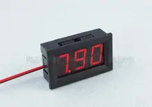
(6) Voltmeter, moving coil
(7) Ammeter moving coil
(8) High power resistors (bolt down)
(9) Power supply connector harness (two off)
(10) 12V Power Supply Test Set (PSTS) power supply

With the exception of the case (1) and heatsinks (2), all the items are available at a relatively low cost from the net. But the case and heatsinks, although available, will be relatively expensive. On the other hand, if you repurposed a case from another piece of equipment and, with a bit of mechanical ingenuity, you could assemble the hardware at little cost.

Moving coil meters are nice- I like them, but from a technical point of view, and probably cost point of view, digital meters would be superior. Digital meters would also be easier to read.

I would suggest that relays will be required rather than direct switching of the load resistors.

A bit of extra electronics will be required to provide an 'On' signal to turn the computer power supplies on- you should really test that function on the computer power supplies.

Some computer power supplies need a minimum current drain to function, so that will need to be taken into account.

If you would like my advice, forget about the electronics, one/some of us should be able to sort that, and think about the case, heatsinks, mounting of resistors, fans, switches, relays, and meters. You will probably find that the case and heatsinks will be bigger/heavier than you first imagined.

This sounds like a fun project with lots of heavy electrical engineering and a low technical risk.:cool:

spec

Links (notional for illustration only at this stage)
(1) Power resistors: **broken link removed**
(2) Voltmeter: **broken link removed**
(3) Ammeter: https://www.aliexpress.com/item/DC-...lt&btsid=683c5234-6f8c-482e-a4cc-82f0954296ce
(4) Switch: https://www.aliexpress.com/item/2-p...lt&btsid=d5518228-6bee-4008-b8ed-b10cf8ed1627
(5) Relay: https://www.aliexpress.com/item/40A...2650296985.html?spm=2114.40010308.4.28.wgub1g
(5) Fan: https://www.aliexpress.com/item/Yat...lt&btsid=ff54c084-2b93-45aa-8b26-484b74ae7f38
(6) 12V Power Supply: https://www.aliexpress.com/item/WSF...lt&btsid=59656f8f-66d3-4e0e-b815-3786c8729dfe
 
Last edited:
spec has good ideas . Mike perhaps we need to understand your budget, purpose, skill set and motivation to match an appropriate solution. This can be a full meal project that can cause indigestion or a learning experience with new tricks or a well designed rig made with passion and experience. But it will take time, effort and money or skill and clever repurposing. pick one.

Myself , I would suggest using a Mobo BIOS with the Voltage monitor screen and use loads on all the HDD ports to verify results. Then use switched load or Pot controlled Active Current sink with a current sense to a meter to 500W on 5V +12v with smooth control and a switch with transistors on an oil filled radiator heater or old CPU heatsinks repurposed as dynamic loads with thermal feedback to CPU monitor. Using 3 stage power Darlington, a pot with 0-10mA input can control 0 to 100A outputs
 
Last edited:
DC-100V-10A-Voltmeter-Ammeter-Blue-Red-LED-Amp-Dual-Digital-Volt-Meter-Gauge-TOP-Quality.jpg_50x50.jpg

1pcs-Top-Quality-DC-100V-50A-Voltmeter-Ammeter-Blue-Red-LED-Amp-Dual-Digital-Volt-Meter.jpg_220x220.jpg

From my side of the pond there are the same price.
Top one is 100V & 10A and the bottom one is 100V & 50A. It only takes one resistor change to make it 10V.
This third one is very low cost.
1pcs-Instruments-Red-LED-Mini-Digital-Voltmeter-DC4-5-120V-Panel-Volt-Meter-4-5V-To.jpg_220x220.jpg


Spec,

I would use a 8 position or 16 position binary switch + 3 or 4 relays + binary resistors. (2,4,8,16 ohm)
But now that I think about it your switch + a hand full of diodes and you could have the same effect.
 
Hi,

With a rotary switch i would use relays too. Simpler to set up and use. Transistors complicate the load calculation.
 
Status
Not open for further replies.

Latest threads

New Articles From Microcontroller Tips

Back
Top