Continue to Site

Welcome to our site!

Electro Tech is an online community (with over 170,000 members) who enjoy talking about and building electronic circuits, projects and gadgets. To participate you need to register. Registration is free. Click here to register now.

  • Welcome to our site! Electro Tech is an online community (with over 170,000 members) who enjoy talking about and building electronic circuits, projects and gadgets. To participate you need to register. Registration is free. Click here to register now.

Components doubts

Status
Not open for further replies.

2PAC Mafia

Member
Hi,

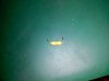
one of them is a fuse, only marking 2000 at the component, is it a 2A?

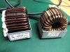
The other are PFC chokes, one of them is saying Elmax, in Italy, I still have to contact them. They are 220uH 16A, do you know a place to find them? The real measure when is working correctly is 216uH and 18Q.
 

Attachments

  • 1 IMG_20151028_220118.jpg
    1 IMG_20151028_220118.jpg
    80.2 KB · Views: 209
  • 1 IMG_20151028_220206.jpg
    1 IMG_20151028_220206.jpg
    36.3 KB · Views: 191
All sorts of vendors for the chokes, 2PAC, although maybe not at your location. Here's one vendor: https://datasheet.octopart.com/PFC-01102-00-Precision-datasheet-8879182.pdf

What equipment are you repairing the needs power factor correction chokes?. Or are they used for somethings else?. Seems I recall you do a lot of large pleasure craft electronics repair.

Don't know about the yellow fuse thingy, if that is what it is.

<EDIT> Just had a look at PFC chokes of that size and I see they're used in low (<1000W) inverters.
 
Last edited:
Thanks Cowboybob,

All sorts of vendors for the chokes, 2PAC, although maybe not at your location. Here's one vendor: https://datasheet.octopart.com/PFC-01102-00-Precision-datasheet-8879182.pdf

There is one for 220uH 20A (I peak), now I don´t know if the 16A I see on the label are RMS or peak, probably RMS...

What equipment are you repairing the needs power factor correction chokes?. Or are they used for somethings else?. Seems I recall you do a lot of large pleasure craft electronics repair.

These chokes are used in professional fitness equipment, an Italian brand called Technogym, I have now 6 units to be repaired and I see some of them have problem at PFC circuit which has to stabilize the 230Vac in 400Vdc bus. Usually I repair units from nautical industry but also fitness industry and general industry electronics.

Don't know about the yellow fuse thingy, if that is what it is.

That is a fuse, it´s just at 12Vac input at a JSST door access control (I think they are korean or japanese), it´s just before a rectifier diode and marked on the board as a F1. I had a short circuit at a 12 to 12 1W DC/DC converter which supplies 0,8A at its output so it has sense the fuse is 2A (marked in mA = 2000).
 
Not sure about the fuse, but from your info I'd say it was 2000ma yes.

The chokes, what makes you think these have failed?, chokes are electrically very hardy and only really fail if you cook them or subjet them to a high enough surge to melt the wire.
In your situation if I had one that was open circuit I'd meaure the wire dia, get a new roll and rewind them, theres only a couple of dozen turns.
One thing to bear in mind if they have been super hot the core material could change its properties, if they had been that hot though they'd have burned a hole in the board.
 
Hi Dr Pepper,

Not sure about the fuse, but from your info I'd say it was 2000ma yes.

The chokes, what makes you think these have failed?, chokes are electrically very hardy and only really fail if you cook them or subjet them to a high enough surge to melt the wire.
In your situation if I had one that was open circuit I'd meaure the wire dia, get a new roll and rewind them, theres only a couple of dozen turns.
One thing to bear in mind if they have been super hot the core material could change its properties, if they had been that hot though they'd have burned a hole in the board.

I was thinking the same but I have some boards where I don´t get the 400V needed from the PFC circuit. The controller of the PFC is a L4981AD and also I have 5 LM358, HCF40106 and an AD633, of course resistors, capacitors, transistors, diodes... All is SMD so I didn´t make the schematic as it´s also multilayer board.

I was testing the chokes, where I have the 400V working all the coils showed me 216uH (220uH is written on the label). On the boards where I had problems on the PFC I got 196uH (two of them) and 209uH. I was working on the SMD area, replacing the IC´s because it was difficult to test measuring, my test was always measuring at pin 20 from L4981AD where I should get the gate driver. I didn´t get it. On pin 19 I get the power 15-16V.
I connected power with my power supply at this PFC circuit (without Vac input) and then I saw there were problems looking at consumption. A good one was always 50mA and then I got at damaged ones: 90mA, 400mA, 200mA. OK, then I decided to replace IC´s and do measuring test in diode testing comparing a good one with bad ones for the rest of components, all good.

After changing all components in one of them I got 520Vdc!!! Something wrong again, and then I was thinking about the inductance from the choke, may be it´s calculated for some exact value and if it changes (lower value) then you get more voltage at PFC. In fact, one of them with 209uH at its choke had an alarm Overvoltage (customer information when the unit is installed at the machine).

I think about all of this but I´m not 100% sure. I can do a test also putting a "bad" choke at a board with a good PFC circuit but I was doing already changes and then I had other problems so it´s a little bit complicated.

Always the same problem, no schematics, no information, no support so that makes things more difficult...
 
Makes sense, depending on the supply topography a lower value inductance may produce a higher voltage, the pf stage being boost is probably a typical boost converter, so reducing the inductance will increase the current ramp, however the system will have feedback to monitor and automatically control the o/p voltage, and there will most likely be a reasonable margin of tolerance, the variances your talking about to me are not really high enough to cause a problem.
The inductors may have something up with them, however it would take more than a slight change in inductance to mess things up as much as you've been getting.
If you got 525v then I'd be thinking theres a problem in the feedback circuit, if you look at the datasheet for the L4981AD then you'll find which pin is feedback, then you can trace the comps from that pin to the o/p, there may be some filtering or compensation, these are the comps to look at, and the pssibility of dry or bad joints.

Thanks Dr Pepper, I guess the best possibility is to use a "bad" choke again in a repaired board. I have repaired three of them now with problems at this circuit, but to test them I used a "good " choke from another board.
I was thinking the value from a "bad" choke is less than 10% difference comparing to a good one but I was not sure if that was enough to create a problem. I can take again the risk to damage the board again using the choke and see what happens there. I think some LM358 was damaged at one, at another I found a HCF40106 damaged, I replaced the LM358 at all of them, testing the L4981 and AD633 in a good one to be sure the components were not damaged.

I was playing with a lot of SMD components, doing changes and comparing things, who knows if on the one where I had 530V I did a bad soldering or something similar. At least know I now three of them where I didn´t have the 400V I repaired getting again the PFC voltage, but still with the doubt about the value of the chokes.
 
The controller is able to modify its pwm to regulate the o/p voltage, there will be an amount of leeway, and as a guess I'd say its more than 10%, esp at low loads.

The only thing I can think of that would wreck a choke in your application is if the supply is overloaded or the design is insufficient and the choke gets very hot and changes its magnetic properties, it would need to get to around 200 degrees for this to happen, and if it did it'd probably take out the fet and a few other bits with it.
At a guess I'd say the lf358 is a current sense amplifier and the 40106 schmitt device may be being used to drive the fets, or as a seperate oscillator.
 
Status
Not open for further replies.

Latest threads

New Articles From Microcontroller Tips

Back
Top