Electric Rain
New Member
Ok... I'm having a small problem... I need to make something that will carry out some commands based on two inputs, and I've done much work on paper and in my head trying to think of a way to do it using relays.
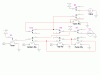
The whole circuit needs to run on a timer, when the timer turns on, the circuit will activate. I'm going to use it in a small tank of water. I have a circuit that will work as the switches for this project. One sensor will be at the bottom of the tank, the other will be near the top. Only one wire will run from them, as the ground will be connected to the bowl itself because it will be metal. This circuit will activate a relay when the water hits the bottom sensor, and a different relay when it hits the top one.
So, I need the circuit to do this: When it turns on, if the bottom or the bottom and the top relays are active, then "Device 1" needs to activate, until the relay(s) is/are no longer active. Then, "Device 2" needs to activate then deactivate when both relays are active again. However, if when it turns on, neither relay is active, then it simply activates device 2, until both relays are active.
The relays can be SPST, SPDT, DPDT, DPST, latching, normally open, normally closed, anything they need to be. As long as they're 12V relays.
It sounds simple, but if you start trying to figure it out on paper, you're going to go... wow... shoot... wait... but if I... no... because it's not as simple as it sounds. :lol: I had some trouble with this little thing and I thought I had it at one point, 'till I went over it again and said... no...no...no...no..no..no!
I can explain it in non-electronic terms too. When the timer turns on, I need it to drain the water using a small 12V pump I found, (if there is water in it) then I need it to fill it back up using a small 12V valve I found.
Thanks for the help if anyone is going to give it.")
Rain
The whole circuit needs to run on a timer, when the timer turns on, the circuit will activate. I'm going to use it in a small tank of water. I have a circuit that will work as the switches for this project. One sensor will be at the bottom of the tank, the other will be near the top. Only one wire will run from them, as the ground will be connected to the bowl itself because it will be metal. This circuit will activate a relay when the water hits the bottom sensor, and a different relay when it hits the top one.
So, I need the circuit to do this: When it turns on, if the bottom or the bottom and the top relays are active, then "Device 1" needs to activate, until the relay(s) is/are no longer active. Then, "Device 2" needs to activate then deactivate when both relays are active again. However, if when it turns on, neither relay is active, then it simply activates device 2, until both relays are active.
The relays can be SPST, SPDT, DPDT, DPST, latching, normally open, normally closed, anything they need to be. As long as they're 12V relays.
It sounds simple, but if you start trying to figure it out on paper, you're going to go... wow... shoot... wait... but if I... no... because it's not as simple as it sounds. :lol: I had some trouble with this little thing and I thought I had it at one point, 'till I went over it again and said... no...no...no...no..no..no!
I can explain it in non-electronic terms too. When the timer turns on, I need it to drain the water using a small 12V pump I found, (if there is water in it) then I need it to fill it back up using a small 12V valve I found.
Thanks for the help if anyone is going to give it.
Rain

 But there's a couple flaws. I'm sure they can be worked out though. And, like I said, it's still a great help. :wink:
 Sorry about that. I would have posted much earlier, but I've been kinda busy lately.

