Hi everyone, thanks for taking some time and helping me out
Im trying to make a new trunk light for my car. I read using 1W LED's with resistors is A) not very smart because of a vehicles voltage fluctuations, and B) the resistors for 1W LED's would create alot of heat and wasted energy.
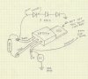
So I have spent a couple hours reading on how to wire an LM317T with 1, 2 or more 1W LED's off a car system.
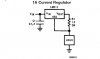
I understand you have to wire a resistor somewhere between pins to adjust current regulation. What I dont understand is 1) where to wire this and b) how a resistor to adjust CURRENT output, will somehow also get the lm317 to output 3.3V from 12-14v?
Lets say I used a 3.9ohm resistor, to make 321ma output ( which is close to the 300 required for my 1W LED's ) however although it is now putting out 321ma, at what voltage and how does it magically match the LED's requirement?
And of course one more thing, how would I wire 3 of these onto 1 LM317 so I do not need 3 voltage regulators and heatsinks?
Thanks very much in advance your really helping me! I want to understand.
Im trying to make a new trunk light for my car. I read using 1W LED's with resistors is A) not very smart because of a vehicles voltage fluctuations, and B) the resistors for 1W LED's would create alot of heat and wasted energy.
So I have spent a couple hours reading on how to wire an LM317T with 1, 2 or more 1W LED's off a car system.
I understand you have to wire a resistor somewhere between pins to adjust current regulation. What I dont understand is 1) where to wire this and b) how a resistor to adjust CURRENT output, will somehow also get the lm317 to output 3.3V from 12-14v?
Lets say I used a 3.9ohm resistor, to make 321ma output ( which is close to the 300 required for my 1W LED's ) however although it is now putting out 321ma, at what voltage and how does it magically match the LED's requirement?
And of course one more thing, how would I wire 3 of these onto 1 LM317 so I do not need 3 voltage regulators and heatsinks?
Thanks very much in advance your really helping me! I want to understand.
")