Continue to Site

Welcome to our site!

Electro Tech is an online community (with over 170,000 members) who enjoy talking about and building electronic circuits, projects and gadgets. To participate you need to register. Registration is free. Click here to register now.

  • Welcome to our site! Electro Tech is an online community (with over 170,000 members) who enjoy talking about and building electronic circuits, projects and gadgets. To participate you need to register. Registration is free. Click here to register now.

Comparing 2 sinusoidal signal

Status
Not open for further replies.

Chaud

New Member
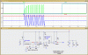
Hello people! I am doing a project , where a part of it consists in a metal detector. The terminals of the coil is usually with a sinusoidal signal of 1.4 V peak to peak, and when it feel the presence of metal, the sinusoidal signal drops to 1.26 V peak to peak or even less (if the metal is greater). What do I need to do is how can I compare the sinusoidal signals? To further send to a microprocessor and it indicates on the LCD.

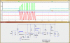
Basically the process is this: If sinusoidal signal => 1.4 Vpp ==> LCD -> "None detected" if sinusoidal signal <= 1.26 Vpp ==> LCD-> "Metal detected."

I had to study using a comparator with hysteresis 741 opamp, but the theoretical values ​​are very different from real, or else I'm doing some bad connections, I believe that this is basic, anyone can teach me how do I make a simple circuit to make this comparison ?

Thank you for your help,
Chaud
 
hi Chaud,
The main problem is the 741 OPA, they can only have an voltage output change of +1.5V to Vsupply-1.5V, when powered with a single supply.

The LM393 dual comparator could be set to detect the sine wave level to give a yes/no reading
 
Last edited:
Hello eric, i have de LM393, now my problem is to get the circuit. In voltmeter in ACV it says:when metal is not present = 0,96V, when metal is present = 0,42 V, i think is with this numbers i need to work right?

So how i make the circuit now? i need to have VTH=0,8V, Vref=0,7V and VTL=0,6V, something like this right?


(btw about supplys i can have more than one)

hi,
I will post a circuit for a LM393 within 24 hrs.
EDIT:
This circuit uses both halves of the LM393 dual comparator.
The 1st Stage is a sine wave comparator, which give a pulse output when the Sine signal amplitude exceeds the Sine Threshold.

The 2nd Stage rectifies the pulses into a DC signal, the DC threshold signal level can be set.

When the DC signal is LESS than the DC threshold the output of the 2nd Stage goes high.
When the DC signal is higher the output is low.

A high drives a transistor output stage.

For demo the transistor drives an LED, the led could be replaced with a small DC tone buzzer, the buzzer would sound when the Sine signal is LESS than the Sine threshold.

The two control pots enable a wide range of threshold settings.

Ask if you need more help.
 

Attachments

  • chaud1.gif
    chaud1.gif
    45.9 KB · Views: 201
Last edited:
Hello, thank you :)

btw i did a circuit with random values with 741, just for test, VTL=1v, Vref=2,2V and VTH=3,4V.
R1=1k (in IN+) and a R2 between IN+ and Vout. And it worked well, but i used DC signals, my doubts are all focused in the fact that im working with AC signals, using my example if i got AC signal with 8Vpp, 4Vmáx, the ampop will perma switch between L+ and L-, because when signal reachs 4V it go L+, then signal reachs 0,5V it go L- , because its a sinusoide signal, you get my doubt? sry for bad english.
 
hi,
I will post a circuit for a LM393 within 24 hrs.
EDIT:
This circuit uses both halves of the LM393 dual comparator.
The 1st Stage is a sine wave comparator, which give a pulse output when the Sine signal amplitude exceeds the Sine Threshold.

The 2nd Stage rectifies the pulses into a DC signal, the DC threshold signal level can be set.

When the DC signal is LESS than the DC threshold the output of the 2nd Stage goes high.
When the DC signal is higher the output is low.

A high drives a transistor output stage.

For demo the transistor drives an LED, the led could be replaced with a small DC tone buzzer, the buzzer would sound when the Sine signal is LESS than the Sine threshold.

The two control pots enable a wide range of threshold settings.

Ask if you need more help.

Hey, thank you very much, but i have some questions about it, FS or V2 = my input signal from bobine right? Where i get the final signal to send to micrprocessor? edit: im studying it now, thanks for circuit!
 
Last edited:
hi,
Fs is the input signal.

The output signal to the micro is from 'vo'...

Note:
this circuit uses a 5V supply which makes the Vout [MCU] compatible 0V/+5V
 

Attachments

  • chaud2.gif
    chaud2.gif
    42.6 KB · Views: 199
Status
Not open for further replies.

Latest threads

New Articles From Microcontroller Tips

Back
Top