Continue to Site

Welcome to our site!

Electro Tech is an online community (with over 170,000 members) who enjoy talking about and building electronic circuits, projects and gadgets. To participate you need to register. Registration is free. Click here to register now.

  • Welcome to our site! Electro Tech is an online community (with over 170,000 members) who enjoy talking about and building electronic circuits, projects and gadgets. To participate you need to register. Registration is free. Click here to register now.

Compare Arduino ADC to 16 bit ADC Chip

Status
Not open for further replies.
Comparing an 8-bit microcontroller ADC to a dedicated 16-bit ADC chip. Not fair!

Hi MisterT,

He he, yeah that is one way to look at it.

The other way is it's just a way to characterize the 328 internal ADC. We need a decent measurement to be able to determine how the device under test compares to something that is known to be good.

I've got several data points from yesterday now, i am going to analyze that data next.
 
Hi,

Here are the test results from the input voltage sweep.
I missed reading some other posts after MisterT's but really 'fair' is not the issue here, knowing how the ADC measurements compare to what they really are is what matters. In the real life app we need to know if our measurements are accurate or not, and we dont care if there are better ADC's on the market or not.

The following test results shows the linearity isnt too bad but the 328 has a nasty offset.
"Red" shows a commercial meter results.
"PWM" is the pwm set count on the 328P which is used to generate the (heavily filtered) analog DC test signal.
The PWM "to" lines show the change from one PWM set point to the next up.
The first numerical entry in each line is the difference of the results with the next PWM setting to the reading with the previous PWM setting.
The second entry in each line is the division of the results with the next PWM setting to the previous PWM setting.
At least 60 seconds between PWM changes to allow plenty of time for all ADC's to settle out.

Test results:
Code:
PWM param change: 10 to 50...
  Red: 0.757000  6.914063
  ADC16: 0.757770  6.661760
  ADC328P: 0.762110  5.114843
  PWM: 40.000000  5.000000

PWM param change: 50 to 100...
  Red: 0.953000  2.076836
  ADC16: 0.951950  2.067675
  ADC328P: 0.954300  2.007368
  PWM: 50.000000  2.000000

PWM param change: 100 to 150...
  Red: 0.948000  1.515778
  ADC16: 0.948590  1.514543
  ADC328P: 0.950090  1.499621
  PWM: 50.000000  1.500000

PWM param change: 150 to 200...
  Red: 0.952000  1.341709
  ADC16: 0.951470  1.340766
  ADC328P: 0.952420  1.333982
  PWM: 50.000000  1.333333
 
Last edited:
I would not think Vcc would be a very good reference, too much noise, voltage variation over temp. You can supply a external Vref to the Aref pin on one of the headers of the UNO board. The Maxim 6126 is available in 2.048V, 2.500V, 2.800V, 3.000V, 4.096V, and 5.000V output voltages with a +/- .02%
I think the internal 1.1v ref is +/- .1vdc.
That is if you really care? the link for the datasheet: https://www.maximintegrated.com/en/products/analog/voltage-references/MAX6126.html
Well at any rate have fun:)
 

Attachments

  • atmegavREF.GIF
    atmegavREF.GIF
    6.3 KB · Views: 226
I told you a ardunio uno is not made to use the adc as it should be they left out a part. They had this talk about the adc being off from what it should be. The amega uses a TANK CIRCUIT but it's not on there and it has noise canceling built into the atmega the LC tank helps hold AVCC level.
But without it the ADC does not do as good a job. Most people just tie it to vdd and some add a cap. But I have not seen any with the inductor as the data sheet tells you to do.

But really this all boils down to how well you set up to take your readings. How well you plan your hardware. And if you have you fluke calibrated. Oh and don't forget to calibrate your ADC. everything needs a little calibration sometimes.
 
Last edited:
Hi again,

Yes i am using a rather expensive meter to calibrate with that does over 50000 count.

But after reading Mike's post and yours i see now it would be better if i hunkered down and did this right, then test. I have some references that are very good so i can use one of those. I also need to run though a calibration routine and then test again. This will help eliminate any obvious defects. If it works after that then i'll be good to go.

I wanted to make this comparison for a long time now but didnt get around to it until recently. But yes, it deserves more time and care before making any final decisions.
I'll read up on the ADC problem in the 328 if i can find it.
 
I am sure the ATmega328 ADC works well when used per the datasheet. The UNO board should be revised to properly use the AREF pin, and have a 2 pin test header as close to the AREF pin as possible. Then again precision may not be the intended use of the UNO?
 
The atmega has two pins AVCC and AREF. The AVCC is what's used to supply power for normal adc use. The chips has built in noise cancelling. The AVCC is to be tied to to VDD with a 10 uH inductor. And having the ADC supply brought outside the chip lets you have better supply power and have a nice adc ground plane. Shows it in the data sheet.
If you want to use something else you supply that to the AREF pin.
 
Hi,

Yes thanks, i might have to try that eventually. It depends what results i get after a few more tests after some calibration. Right now i am testing some other things too.
I tested the PWM output too but it seems to drift or something. Sometimes the average output (well filtered) is 1.000vdc, sometimes 0.998vdc, sometimes 1.020vdc, all with the same PWM param set to 55 decimal. Not as stable as i would have liked, but i havent investigated this entirely yet.
 
Hello again,

Little update...

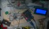
I have found that one of the main problems is the Arduino connectors and the little plug boards that are often used for prototyping. The connection to the plugboard is somewhat variable, so that the reference voltage and/or ground can be changing by as much as 80mv, which is a lot for an analog project. This means the reading will always vary.

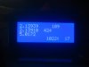
To test, i used a 3 point, 4 digit calibration scheme with a second order fit, then compared readings. The readings match one time, then dont match another time. If the power is turned off and then back on, it might read as much as 10mv difference. If the wires are just moved slightly, it might read 20mv difference. Calibrating a second time shows the same behavior, so the main problem is the connections between the 328 chip and the power supply ground and/or +5v line.

So the lesson here is that the plugboards are not any good for serious analog as well as high frequency projects. This little project will have to be all soldered together for better repeatability and proper testing.

An interesting point here is that the plugboard circuit draws very little total current, yet the connections to that board are still important. For example, the filter draws less than 1ma. You would think that would not form much of a voltage drop because even in 1 ohm (which would be high for a short wire and connection) it would only drop 1mv.
 
By plug in boards are you referring to the shields? I have found that the headers can be malformed by over size gauge conductors, (My PSoC board has same headers). This results in poor connections, may need to replace header if this is the case.
so the main problem is the connections between the 328 chip and the power supply ground and/or +5v line.
Are you talking about Vcc? That should be pretty solid, it comes from a regulator, or are you talking about a power supply connection to you UNO Vref pin? If the latter, this would not be the way to go (long or even short wires no bueno). To generate an external Ref voltage, I would make a little PCB with a precision reference voltage IC, and have the little PCB plug right into the header. Unfortunately the Vref header does not have a Vcc pin, so your board (shield) would need another header plug to get the power connection. This would be the ideal way to go. While you at it, you could add other doo dads to your shield. I am having trouble picturing your setup, maybe you can post a pic?
 
Hi Mike,

Yes i have found that plugging in a "shield" will bend the header pins on the Arduino board so that regular jumpers do not stay in as tightly anymore.

What i did was soldered two wires right to the Ard board itself, one to +5 and one to ground. They run to the plugboard (solderless breadboard).

I think the +5v regulator is solid, it's still the connections on the breadboard that must be causing the problems. I also added what they call a "prototype shield" which helps with the 'used' header problem for clock and data lines. It also breaks out the +5 to five more header pins and five more ground header pins.

I am planning on soldering a few connections later today rather than use the plugboard for everything to see if that helps. I think it will. At least for the +5v and ground, the rest is probably OK in the plug board because it is fairly high impedance stuff.
We'll see i guess :)

Thanks for the ideas.

Here's a quick snapshot of the setup...
 

Attachments

  • Setup-1.jpg
    Setup-1.jpg
    141.3 KB · Views: 217
Last edited:
Recently I had issues with a PIC 10bit ADC sampling (8 x oversample) being inconsistent. Without going into the long story of discovery (changing chips etc) it turned out to be 2 things.
1) The 5.12 Vcc power ref was not stable because of using regular signal (board to board) header/jumper wiring (dual female jumpers to dual male hdrs) which could cause a little voltage issue with both the Vcc and ground return, about 100mA draw. The circuit was subject to fan cooling which 'vibrated the wires a bit' introducing some random resistance induced voltage 'noise'.
The quick solution to that was to use a PAIR of jumpers for each rail. Recently I have upgraded that circuit to use molex friction lock connectors and the wire to board jumpers are direct soldered to the source, instead of source headers.

2) A LM324 jelly bean OPA was used as a difference amp with two input buffering amps, like an instrumentation unit. Because the calibration pot only varied ONE of the TWO gain control resistors the apparent slope of the gain was also varied with the bottom range being affected more than the top. This was not due to LM324 limits as the diff. amp output range was well inside rail to rail and class B. (0.5V to 4.5V , 12Vcc)
The solution required adjusting the gain to get the linear slope (m) right with the trimmer and then using an offset factor (c) in firmware, accessible via a pushbutton setup; y=mx+c. The offset correction is important since the LM324 introduced 3mv (measured) of offset when comparing the unity buffers, plus resistor tolerance has to be compensated for.
Also, any calibration should be done after 10 minutes of 'warm up' to steady state.

Final overall accuracy was around +/- .02V after 4x firmware scaling (2V to 18V) as measured by a new Fluke 87V.
 
MrAl:

When the sensors output is ratiometric to the supply voltage such as with these, **broken link removed** the reference does not have to be right on and it means it should be the supply voltage.
 
Last edited:
Here I'll let you use a Pic that can run arduino code and use there shields see how they fare.
The board using a hid boot loader and runs pinguino they don't have a lot of chips to use this ones a 18f2550. https://www.pinguino.cc/ It works ok but I'm loading code complied with swordfish basic.
 
MrAl:

When the sensors output is ratiometric to the supply voltage such as with these, **broken link removed** the reference does not have to be right on and it means it should be the supply voltage.

Hi,

I happen to be well aware of how sensors work, but i intend to use this for absolute voltage measurement mostly. That is, measuring the voltage of a battery, power supply output, etc.
 
Here I'll let you use a Pic that can run arduino code and use there shields see how they fare.
The board using a hid boot loader and runs pinguino they don't have a lot of chips to use this ones a 18f2550. https://www.pinguino.cc/ It works ok but I'm loading code complied with swordfish basic.

Hi,

That's cute. Not sure i will get around to trying that board or not. Seems kind of limited though. I was looking at the "Due" last night a little. 32 bit ARM core, 85MHz i think.
 
Hi,

Finally got this thing somewhat calibrated, although i'll have to repeat of course when i move to an actual permanent circuit board.

The top left reading is the 16 bit ADC, the next down is the 328P chip ADC, the next down is the 5v supply line measured against the 1.1v internal reference calibrated with a 4 digit volt meter (wanted to keep track of the 5v line actually getting to the chip itself rather than somewhere off in the distance on another board).
This also had shown me that the breadboard voltage changes up and down by at least 20mv while the Arduino PC board voltage doesnt chance much.
Better results overall however after soldering a ground wire right to the PWM filter cap ground lead. The breadboard connections just were not good enough for whatever reason.
 

Attachments

  • ADC_Display-2.jpg
    ADC_Display-2.jpg
    57.2 KB · Views: 217
Yes, mV reliability requires solder joints or quality gold plated connectors without jumper vibration.
 
Status
Not open for further replies.

Latest threads

Back
Top