Continue to Site

Welcome to our site!

Electro Tech is an online community (with over 170,000 members) who enjoy talking about and building electronic circuits, projects and gadgets. To participate you need to register. Registration is free. Click here to register now.

  • Welcome to our site! Electro Tech is an online community (with over 170,000 members) who enjoy talking about and building electronic circuits, projects and gadgets. To participate you need to register. Registration is free. Click here to register now.

Comparator not working with transistor

Status
Not open for further replies.

bradsk88

New Member
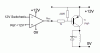
I'm using an LM741 as a comparator, and on its own it works great. I can get it to switch on an LED under the appropriate conditions like clockwork.

I also have an NPN transistor wired up to activate a relay when I apply 12V to it's collector. On it's own it works fine, applying 12V turns on the relay.

But if I hook the output of the LM741 to the collector of the transistor it doesn't work. I've placed a logic probe on the wire and it sits at ground at rest, when I try to activate it the output of the LM741 goes open.

What am I doing wrong?
 
Normally you apply a signal to the transistor base, not the collector. Need to know where the other terminals of the transistor are connected. Post a schematic.
 
hmm, I don't have the circuit with me right now.

Does it sound like I might have it backwards?

Emitter is connected to relay and there is also a diode to ground for protection.
Base, is far as I know is sitting at 12V constant and
Collector gets a 12V trigger when it needs to be "on".

I suppose I might have B and C backwards, I'll check tomorrow.
 
Last edited:
Yes, you're doing it wrong.

Here's how yo connect up a relay and a transistor, the input goes to the output of the LM741.
**broken link removed**
Incidentally, the 741 isn't the best device to use as a comparator, it's designed to be used as a linear amplifier rather than a comparator. If you need a comparator then it's better to use a device specifically designd for the purpose such as an LM393 or LM311, the latter can drive a relay without the need for a separate transistor.
 
Okay, looking at my circuit today, I had the transistor wired up properly.

Collector is constant, base is switched.

Even so, it doesn't work.

I'm not sure I understand your schematic. Are you switching the relay with ground? I was intending to switch it with 12V
 
Oh yes, I forgot, the LM741 has a minimum output voltage of 2V, connect a 330Ω resistor from the base to emitter.

Do you have to switch it with 12V?

It's easier to switch ground.

You can switch it with 12V but you'll need to use a PNP transistor, connect the emitter to +V, collector the relay coil and reverse the + and - inputs to the 741.
 
This is what I've got essentially.

untitled-2-copy-jpg.32091


If I were to switch it with ground, I would simply change the circuit to the one you posted but still use the + off of the output of the opamp, correct?
 

Attachments

  • Untitled-2 copy.jpg
    Untitled-2 copy.jpg
    39.8 KB · Views: 2,155
You have it configured as an emitter follower which is fine in some applications but does have the problem of having a large voltage loss.

When the output of the 741 is high, the voltage across the relay with equal 12V - the 741's saturation voltage - the saturation voltage of Tr1 - the base emitter voltage of Tr1. As a rough guess the voltage across the relay will be 12 - 2 - 0.7 - 0.3 = 9V which might not be enough to activate it.

Here's a better way of switching the positive to the relay.

The transistor is now connected in common emitter configuration.

Note that the transistor has been changed to a PNP type and that the input to the op-amp are reversed.
 

Attachments

  • High side PNP relay1.GIF
    High side PNP relay1.GIF
    5.1 KB · Views: 1,935
Status
Not open for further replies.

Latest threads

New Articles From Microcontroller Tips

Back
Top