Continue to Site

Welcome to our site!

Electro Tech is an online community (with over 170,000 members) who enjoy talking about and building electronic circuits, projects and gadgets. To participate you need to register. Registration is free. Click here to register now.

  • Welcome to our site! Electro Tech is an online community (with over 170,000 members) who enjoy talking about and building electronic circuits, projects and gadgets. To participate you need to register. Registration is free. Click here to register now.

Common mode choke for 100MHz to 200MHz is just small NiZn torroid with 1 or 2 turns?

Status
Not open for further replies.

Flyback

Well-Known Member
Hi,
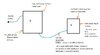
We want to put a common mode choke at the input to a 10W buck (12v to 5v).
We have problems with radiated emissions between 100MHz and 250MHz.
As such all we need is a common mode choke made of a torroid with a turn or two.
And the turns should not be of ECW...(enamelled copper wire) ....because interwinding capacitance will be too high.
The turns should be of eg 7/0.2mm insulated wire, because it keeps distance between the coil metal turns so there is less stray capacitance between them.
So why do all offtheshelf CM chokes for eg 100MHz use ECW (Enamelled copper wire)?

And do you agree with the postulate of this post

Torroid core for use with one or two turns for 100MHz-250MHz radiated emissions...
 
Last edited:
Bifilar winding is often used for the best common mode balance or matching, including at high frequencies and powers. And enamelled copper is extremely common for such things.

I think you are looking for problems that do not exist.

If you are bothered about separation between the two windings, there are plenty that keep the two apart, eg. a couple of designs with well separated windings, to illustrate possibilities.


And if you are so concerned about commercial enamelled wire types, why not just include a ferrite tube on the incoming power connection?
 
I think you are looking for problems that do not exist.

How would you like to be his employer? He evidently got the job by his "experience" but comes to a web forum to get answers from unknown people.
 
Last edited:
Thanks for these
If you are bothered about separation between the two windings, there are plenty that keep the two apart, eg. a couple of designs with well separated windings, to illustrate possibilities.


https://uk.farnell.com/wurth-elektronik/7448040382/common-mode-choke-0-082h-2-5a/dp/2431574


https://uk.farnell.com/laird/cmx1211z680b-10/common-mode-choke-50a/dp/2451889
They do a good job of the go and return separation...but within each coil group the windings are close, and there will be some stray capacitive coupling.
 
Hi,
We have got to pass radiated EMC (30MHz to 1GHz), but in a “real” situation where what we cannot afford “proper” RF EMC techniques…and in truth…”real” EMC techniques just wouldn’t be mandated, or realistic.

Our setup is as attached.

The following doc calls for a “RF Reference plane” for use with EMC filtering and shielding….

…That sinks us from the start. We have two panels, whose metal enclosure is earthed, but that earth comes from the earth wire in the long 3-core power cord…..so that connection is so high Z to RF that its NOT a connection at all. So we have no RF reference plane!!!…and our metal chassis is basically floating at RF !!!

So straight away no official EMC literature is of any help to us!!!

Does anyone have an “EMC guide for real-life, cost constrained situations” document, instead of these “perfect EMC” guides which tell how to do EMC for super-expensive medical devices or military devices with RF gasketted connectors etc? I’ve read tons of them and they are no use.

I mean, Feedthrough capacitors, etc etc aren’t much use without an RF reference plane.

Take the blue cable between the two enclosures in the attached.
What are the options?


(a)…Two core cable unscreened?
(b)…Three core cable with third connector connected to chassis at each end?
(c)…Two core cable with screen…screen left floating…it may as well float…both our chassis’s are already floating at RF?
(d)…Two core cable with screen connected to chassis at “A”?
(e)…Two core cable with screen connected to chassis at “B”?

…and what if we just don’t bother connecting our chassis’s (A and B) to earth at all?....after all, the power cord earth connection is NOT a connection at RF…its too high Z. And then what should we connect our Y capacitors to?....there is no Earth. How are the common mode chokes working at all?

No EMC literature discusses these real options. Do you know the real answers?
 

Attachments

  • Radiated emissions_1.jpg
    Radiated emissions_1.jpg
    98.1 KB · Views: 164
Also, if a battery in A , alone supplies B,. then what if the A's metal enclosure is not earthed?....will it make the radiated emc scan worse?
 
Status
Not open for further replies.

New Articles From Microcontroller Tips

Back
Top